
NSG8000 · Laboratory Configuration Guide
NSG8000 GNSS Lab Testing: Configuration and Coverage Guide
An NSG8000-based receiver test bench needs more than a list of simulator specifications. It needs a defined signal configuration, RF delivery path, DUT preparation, reference truth and a measurement method that answers the laboratory’s test question.
This application guide helps receiver developers, laboratory engineers and research teams map requirements to a proposed NSG8000 configuration, identify external dependencies and decide what evidence is needed before qualification. Use the NSG8000 product page to request current specifications and configuration details.
For the broader learning path, visit GNSS Simulation 101. For a complete project architecture, use the GNSS receiver development and HIL solution.
Which Laboratory Requirements Can an NSG8000 Configuration Address?
NSG8000 is positioned for configurable GNSS RF simulation, receiver development and advanced test integration. Evaluate the actual hardware, software and options against the required cases. Keep current configuration documents with the review rather than relying on a generic percentage of scenarios covered.
| Laboratory requirement | Proposed NSG8000 role | Confirm in the configuration | Additional bench considerations |
|---|---|---|---|
| Multi-constellation / multi-frequency reception | Generate the required GNSS RF signal set. | Exact signals/components, simultaneous combinations, navigation data, channel allocation and licenses. | DUT support, enabled receiver modes, RF passband and signal-use logs. |
| Static and dynamic receiver behavior | Provide a prescribed position or supported trajectory input. | File/interface format, time scale, frames, interpolation and applicable dynamics envelope. | Validated motion data, truth reference point, antenna offsets and epoch-aligned analysis. |
| RF fidelity and measurement confidence | Provide the configured navigation stimulus. | Applicable range/range-rate, power, coherence and phase-noise specifications with their conditions. | RF-path calibration, references, instrument uncertainty and the measurement acceptance rule. |
| Propagation and error-model studies | Apply supported atmosphere, multipath or range-error models. | Model definitions, controllable parameters, combinations and required options. | Representative case selection; modeled behavior does not cover every field environment. |
| Multiple receivers or antennas | Provide shared RF or configured independent signal views. | Physical outputs, independent states, synchronization and any required relative-phase performance. | Splitters, path matching, calibration and the distinction between separate vehicles and antennas on one platform. |
| HIL, integrated navigation or resilience | Form the GNSS stimulus part of the wider test architecture. | Motion protocol, timing boundaries, options, supporting streams and source coordination. | External models/controllers, inertial/correction inputs or dedicated interference/spoofing test sources as required. |
For each row, identify an acceptance check and its owner. A capability listed in a proposed configuration still needs to be demonstrated at the required interface and operating conditions.
Define the Bench Measurement Chain
A typical conducted receiver bench combines scenario control, the GNSS RF source, a characterized RF path, the DUT, receiver logging and comparison with scenario truth. Timing references and real-time motion sources are added when the test requires them.
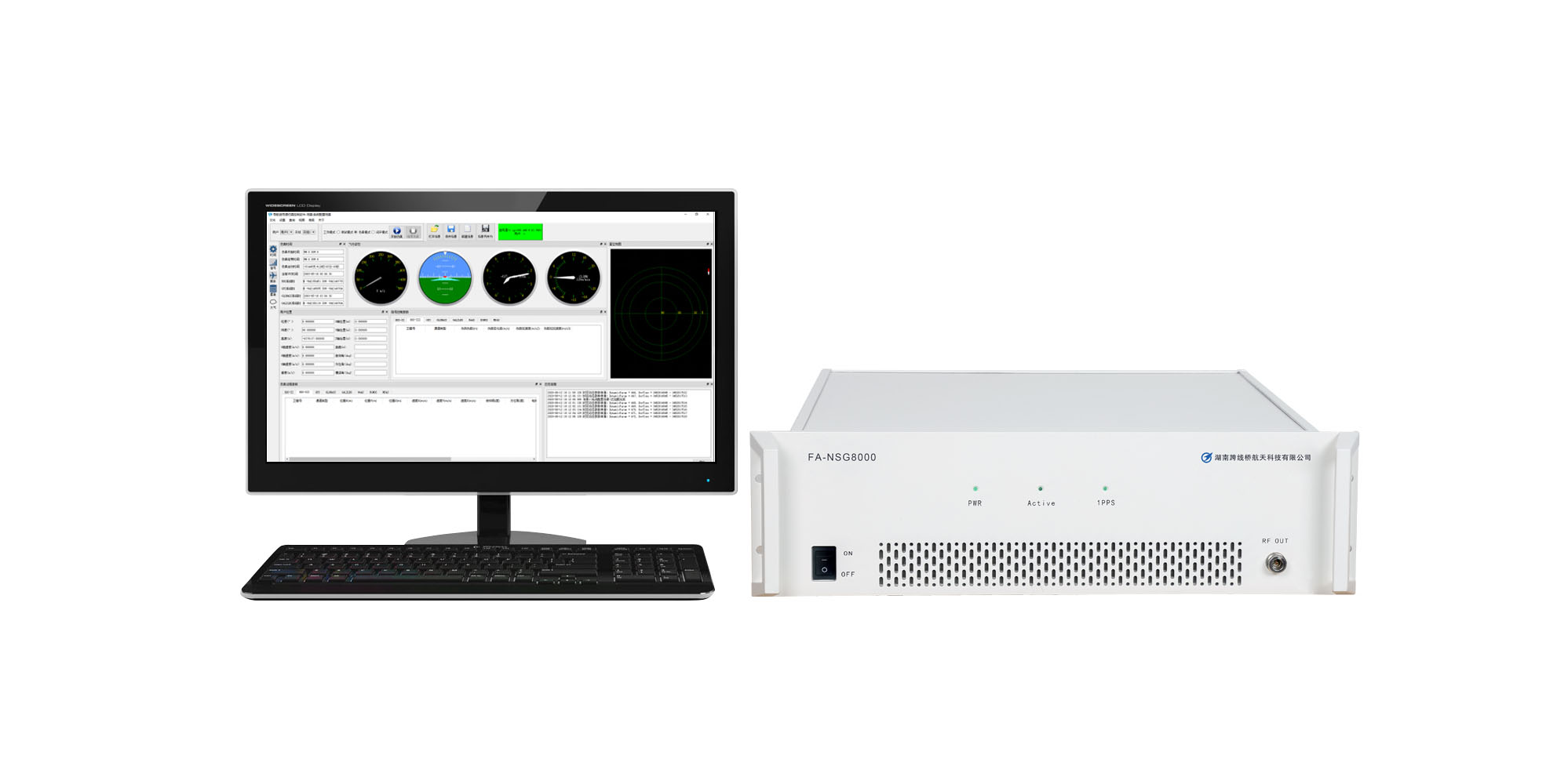
Conducted RF bypasses the DUT’s antenna radiation pattern and some installation effects. Include an appropriate antenna/OTA or field assessment when those effects form part of the requirement. The receiver-testing solution addresses complete bench configuration and integration responsibilities.
Specify Exact Signals and Count Resources Separately
Translate “multi-GNSS” into an explicit signal request
A request for GPS and Galileo dual-frequency testing should identify the required components, not only “L1/L5.” An example requirement might name GPS L1 C/A and L5 I/Q together with Galileo E1 B/C and E5a I/Q. Confirm the simultaneous combination with the selected NSG8000 configuration and the DUT.
Include the scenario epoch, navigation dataset, satellite selection, visibility rules and expected receiver modes. Record which signals were generated, tracked and used in the solution. More enabled signals do not prove they contributed to the result.
Use the GNSS signals, bands and codes guide when preparing the requirement. Confirm extensions and licenses separately; a broad constellation label is not a guarantee of every signal.
Separate channels, satellites, RF outputs and receiver states
A signal-channel count is not a count of independent antenna views. Describe how the platform allocates resources for the chosen signal combination, then state the number of physical RF outputs and independent simulated receiver states.
A splitter can distribute a shared RF scenario to several DUTs. Separate positions, trajectories or antenna observations require the appropriate independent signal-generation architecture. Multi-antenna carrier-phase work additionally requires verified relative phase, delay and calibration through the relevant paths.[4]
Interpret Simulator Fidelity, RF Levels and DUT Accuracy Correctly
Keep source specifications separate from measured receiver error
Simulator pseudorange or phase-noise specifications describe aspects of the generated stimulus under stated conditions. They are not a direct promise of DUT positioning accuracy. Receiver behavior also depends on geometry, processing, enabled corrections, the RF path and the measurement method. ESA distinguishes modeled uncertainty, predicted accuracy and measured positioning error.[1]
Request the applicable conditions for each specification: signal/carrier, reference plane, bandwidth, operating mode, calibration and whether it is a bound, typical value or statistical quantity. A phase-noise value at one offset is one part of RF quality, not a complete sensitivity or tracking result.
Characterize the bench uncertainty separately from the DUT result. Include relevant RF-level, timing, reference and alignment contributions, with correlations where applicable. NIST’s uncertainty guidance describes propagation through a measurement model and the role of covariance.[2]
Example: calculate power at the DUT reference plane
For a passive RF path, delivered power equals source power minus net path loss. Suppose an illustrative path has 2 dB cable loss, 7 dB splitter-path loss and 11 dB attenuation: total loss is 20 dB. A per-signal level of −110 dBm at the defined source plane would therefore be −130 dBm at the DUT plane.
This is a planning calculation, not an NSG8000 specification or a measured result. Confirm supported output settings, calibrated path loss and uncertainty for the actual frequency and setup. State whether levels are per satellite signal or composite; account separately for noise, active components and receiver input limits.
Receiver-reported C/N₀ is an observed diagnostic. It is not interchangeable with a source-power setting, and it depends on noise and receiver processing.
Example: a timestamp mismatch can resemble positioning error
For ideal straight-line motion at a constant 20 m/s, comparing the receiver position at time t with truth at t + 0.1 s creates a 2 m along-track mismatch even if the receiver position is otherwise correct. Align measurement epochs before attributing dynamic error to the DUT.
Keep measurement epoch, packet arrival and application-use time distinct. Use the GNSS metrics guide for output definitions and the error-budget guide for error-model assumptions.
Which Requirements Need Additional Configuration or Equipment?
Trajectory import and real-time HIL
Validate imported motion for coordinate frame, units, time scale, height convention, sampling and interpolation. Confirm the fields required by the selected interface; position, velocity, acceleration and attitude must describe a consistent state when supplied.
For HIL, distinguish state-validity time, packet arrival, processing deadlines and RF applicability. Specify update cadence, input-to-RF latency, jitter, common-time mapping and missing/late-input handling. A 10 MHz or 1PPS connector does not establish the complete timing performance. Safran’s HIL documentation illustrates these timing distinctions for its own implementation.[3]
Real-time injection becomes closed loop when DUT/controller response influences later simulation states. Use the GNSS HIL testing solution and scenario design guide to define that architecture.
Multi-antenna and integrated navigation
Specify antenna reference points, offsets, orientation, independent RF views and relative timing/phase requirements. Shared reference clocks alone do not prove carrier-phase alignment.[4]
GNSS/INS, odometry or differential-positioning tests also need the relevant sensor/correction streams, formats, errors, epochs and synchronization. Confirm which elements are generated, replayed or supplied by external equipment, and who integrates them.
Interference, spoofing and captured field events
Nominal GNSS generation, dedicated interference/spoofing stimuli and RF capture/replay are different roles. Confirm the required sources and coordination rather than assuming they are included in a standard NSG8000 configuration.
Use the receiver resilience testing solution for active RF test architecture, the recording and playback solution for captured RF, and integrated GNSS test systems when several subsystems must operate together.
Saving simulator settings or receiver logs is not the same as capturing an RF waveform. Compare the methods in the simulation, replay and field-testing guide.
Review a Simple Baseline Before Expanding the Test Scope
For an initial single-antenna bench, a static, conducted nominal case is a useful way to check the measurement chain. It establishes bench readiness; it is not a complete receiver qualification campaign.
- Freeze the brief: define DUT/firmware, exact signals, scenario time, static reference point and required output/status fields.
- Check the RF connection: confirm source and DUT limits, antenna-bias/DC requirements, reference plane, routing and calibrated loss.
- Prepare and identify the DUT: apply the documented initialization, record retained data and set the intended navigation/aiding mode.
- Capture comparable evidence: retain scenario truth, receiver PVT/status and available tracking data with defined cadence and time mapping.
- Review before qualification: resolve missing signals, wrong mode, timestamp gaps or RF delivery problems before interpreting performance.
Then add the required motion, power changes or environmental models in controlled stages. Use the receiver validation test plan for repetitions, distributions, acceptance thresholds and reporting.
What Should Laboratory Acceptance Evidence Show?
Separate three decisions: whether the configured source meets its agreed requirements, whether the integrated bench delivers the intended input and evidence, and whether the DUT meets the receiver requirement.
| Decision | Evidence | Conclusion it supports |
|---|---|---|
| Configuration coverage | Agreed signal/options list, interfaces, resource allocation and documented exclusions. | The proposed configuration addresses the stated scope. |
| Source and RF delivery | Applicable verification/calibration records and RF-path characterization at named reference planes. | The stimulus is suitable for the specified measurement, within stated uncertainty. |
| Integration readiness | Time mapping, trajectory/interface checks, truth/log coverage and external-system acceptance results. | The assembled bench can execute and observe the intended test. |
| DUT performance | Raw outputs, trial IDs, frozen scoring, failure counts and requirement-linked results. | The tested DUT meets or fails the declared cases under the recorded conditions. |
Archive scenario and DUT settings, software versions, relevant files/checksums, reference/calibration identities and analysis code. Preserve setup failures and unmet preconditions separately from receiver failures.
If a program invokes a standard, confirm its version, applicable clauses, prescribed method, equipment conditions and evidence requirements. A simulator model name or a general “laboratory-grade” description does not establish compliance.
Prepare an NSG8000 Laboratory Configuration Brief
Start with the DUT, application, exact signals, number of antenna inputs and independent receiver views, motion source and required measurements. Add existing equipment and the initial schedule or deployment constraints.
For advanced work, include HIL protocol/timing, inertial or correction streams, propagation/error models, RF reference planes, automation needs and applicable acceptance procedures. Detailed files can follow the initial requirement summary.
Request a review that identifies the proposed NSG8000 signal/options configuration, external equipment, integration work, verification responsibilities and remaining coverage gaps. Use the NSG8000 product page for model information and how to choose a GNSS simulator when comparing platforms.
Explore GNSS testing applications to relate the brief to the intended operating environment.
NSG8000 Laboratory Testing FAQ
Can one NSG8000 cover every GNSS laboratory test?
Coverage depends on exact signals, models, RF outputs, interfaces, options and the test procedure. Evaluate each requirement and identify external equipment or evidence gaps. There is no meaningful universal coverage percentage without a defined case set.
Does simulator pseudorange accuracy guarantee receiver positioning accuracy?
No. It describes part of source fidelity under specified conditions. Measure DUT error against suitable truth with correct epoch/frame alignment and an understood bench uncertainty.
Can multiple DUTs share one RF output?
A suitable splitter can distribute the same RF scenario, with path loss and connection requirements accounted for. It does not create independent positions, trajectories or antenna observations.
Are HIL and GNSS/INS testing included automatically?
Confirm the selected interfaces, options, motion/sensor inputs, references and integration scope. A complete workflow may include external models, sensors or controller equipment and requires its own timing verification.
Does simulator data logging provide RF record and replay?
Not by itself. Scenario files, truth and receiver logs are different from sampled RF waveforms. Capturing real field RF requires the appropriate recording and playback equipment.
What should be verified before a receiver acceptance campaign?
Confirm configuration coverage, RF delivery, initialization, time mapping, truth, output coverage and scoring. Keep bench acceptance separate from the DUT’s performance decision and the program’s compliance requirements.
Review Your NSG8000 Laboratory Configuration
Share your receiver, required signals, RF architecture and test objectives. Request a configuration review to identify suitable options, external dependencies, interface work and the evidence needed for bench acceptance.
Technical References
- ESA Navipedia: Positioning Error — modeled, predicted and measured accuracy.
- NIST: Combining Uncertainty Components — measurement models and correlated uncertainty contributions.
- Safran Skydel: Time Reference — an implementation example of HIL time mapping.
- Safran: An Engineer’s Guide to CRPA Testing — multi-antenna spatial and phase-alignment principles.
External references explain measurement and architecture principles. Their product features and performance values are not NSG8000 specifications. Obtain current configuration documents and agreed verification conditions for the proposed system.