
NSG8000
Full-featured multi-constellation GNSS signal simulation for advanced R&D, real-time HIL testing, and certification workflows. Supports BDS, GPS, GLONASS, and Galileo — with trajectory import, configurable HIL update rates from 1 Hz to 1 kHz, end-to-end latency of ≤10 ms, and multipath simulation.
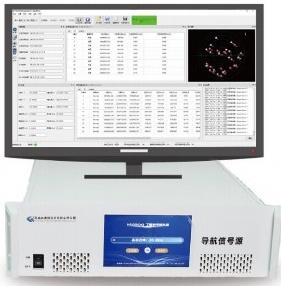
When your program requires certification-grade signal fidelity.
NSG8000 supports BDS/GPS/GLONASS/Galileo signal simulation and can be extended to QZSS and IRNSS. It provides the full signal environment control required for receiver characterization under DO-229, EN 302 645, and program-specific test plans — including ionosphere/troposphere delay modeling, multiple pseudorange models, and real-time trajectory injection.
The platform is designed for engineering teams that need to run the same test scenario multiple times with identical signal conditions — essential for regression testing, performance characterization, and certification evidence collection where repeatability is a hard requirement.
With a 3U rackmount form factor, standard RF/timing interfaces, and optional INS/GNSS integration, the NSG8000 integrates directly into existing test bench infrastructure without requiring custom RF conditioning or timing distribution hardware.
Certification-Ready Signal Environment
Controlled constellation, carrier, and delay parameters meet the signal fidelity requirements of DO-229 and EN 302 645 test plans.
Real-Time Trajectory Injection
Import pre-planned trajectories or inject dynamics in real time — enabling both scripted test sequences and live HIL simulation.
Multipath & Propagation Modeling
4-channel multipath simulation per frequency point, plus ionosphere/troposphere delay modeling for realistic signal environments.
Extensible Constellation Support
Base platform covers BDS/GPS/GLONASS/Galileo/SBAS. QZSS and IRNSS available as software extensions without hardware changes.
Product Gallery
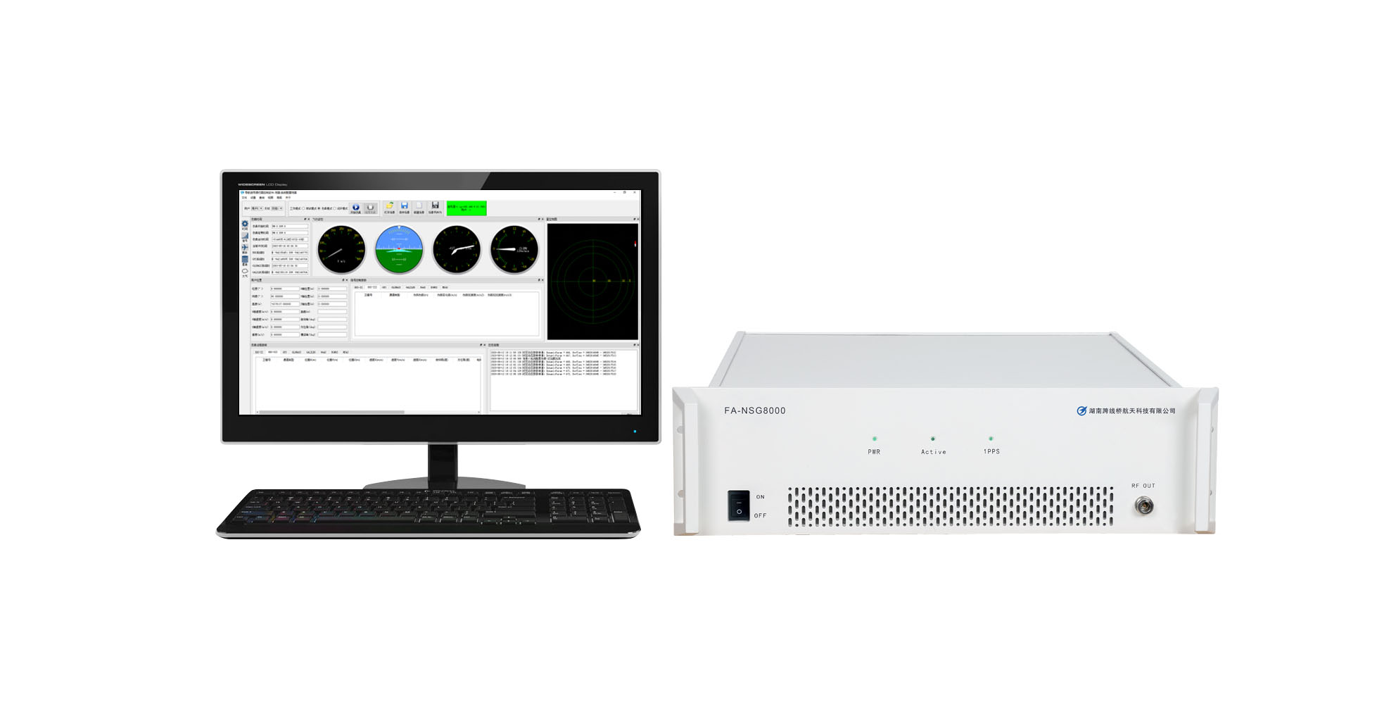
NSG8000 rackmount GNSS signal source views, including front, side, rear panel, screen interface, and PC connection setup.


Six core capabilities that define the NSG8000’s test coverage.
Each capability is engineered to address a specific class of receiver test requirement — from basic signal generation to complex multi-path HIL environments.
Constellation & Carrier Control
Full control over constellation selection, carrier frequency, and signal power for each channel. Supports BDS B1I/B1C/B2a/B2b/B3I, GPS L1-L5, GLONASS L1/L2, Galileo E1/E5a/E5b, and SBAS — with per-channel power control across a 100 dB dynamic range.
Trajectory Import & Real-Time Injection
Import pre-planned trajectory files, including NMEA and custom formats, for scripted test sequences, or inject dynamics in real time via Ethernet/RS-232 for hardware-in-the-loop configurations. Supports static, kinematic, and high-dynamic profiles up to ±200,000 m/s velocity.
Ionosphere & Troposphere Delay Simulation
Klobuchar ionospheric model with configurable parameters, plus tropospheric delay modeling for realistic signal propagation. Essential for testing receiver compensation algorithms and evaluating positioning accuracy under atmospheric variation scenarios.
Multipath Signal Simulation
4 multipath channels per frequency point — configurable delay, power offset, and phase for each reflected signal. Enables realistic urban canyon, indoor, and complex signal environment simulation for evaluating receiver multipath mitigation performance.
Multiple Pseudorange Models
Supports multiple pseudorange error models for different test modes — including clean signal, error injection, and fault simulation. Enables testing of receiver RAIM algorithms, integrity monitoring, and fault detection/exclusion performance under controlled error conditions.
Data Logging & Standard I/O
Continuous data logging with configurable record intervals. Standard output formats for post-processing and analysis integration. 10 MHz reference and 1PPS I/O for timing synchronization with external instruments, enabling multi-system test configurations.
Real-Time HIL &
Multi-Receiver Simulation
Closed-loop GNSS simulation with a defined end-to-end response path, high-rate motion updates, and configurable multi-RF output capability.
Convert external motion data into corresponding GNSS RF signals in real time.
NSG8000 supports real-time hardware-in-the-loop testing by continuously converting externally supplied motion data into corresponding GNSS RF signals.
The system supports configurable HIL update rates from 1 Hz to 1 kHz, with an externally specified end-to-end latency of ≤10 ms from motion data input to RF signal output.
With the optional multi-RF configuration, a single NSG8000 can support up to four RF outputs. Each output can represent a receiver at a different position and under a different motion state.
- Navigation Receivers
- GNSS/INS Integration
- Vehicle Control Systems
- Guidance Algorithms
What “end-to-end latency” means
Complete specification data
for the NSG8000 Series.
Core specifications are shown for the NSG8000 platform. HIL interfaces, RF output quantity, and other optional capabilities are configured according to project requirements.
Signal Types
Supported GNSS signal frequencies and modulations
- B1I, B1C, B2a, B2b, B3I
- Authorized signals (on request)
- L1 C/A, L1C, L1P
- L2C, L2P
- L5
- L1 (FDMA)
- L2 (FDMA)
- E1 (B/C)
- E5a, E5b
- WAAS (L1)
- EGNOS (L1)
- MSAS (L1)
Signal Channels
Number of simultaneous signal channels per constellation
Signal Dynamics
Maximum user dynamics supported in simulation
HIL & Multi-RF
Real-time closed-loop performance and configurable multi-receiver RF simulation
Signal Accuracy
Pseudorange, rate, and channel coherence specifications
Output Level
RF output power range and accuracy
Carrier Phase Noise
Phase noise at various offset frequencies
Time / Frequency Reference
Internal oscillator and external reference specifications
Physical Characteristics
Mechanical and power specifications
Interfaces
Physical connectors and communication interfaces
Three primary test scenarios
where NSG8000 is the right tool.
Each scenario describes the engineering challenge, why a controlled signal environment is required, and how the NSG8000 addresses it.
R&D Validation, Debugging & Failure Analysis
The challenge: Real-world GNSS signals are uncontrolled — you cannot reproduce a specific satellite geometry, signal level, or propagation condition on demand. When a receiver fails in the field, you cannot recreate the exact conditions in the lab.
NSG8000 creates repeatable, controllable GNSS scenarios to reproduce issues and validate fixes across firmware and algorithm iterations. Set the exact satellite geometry, signal levels, dynamics, and propagation conditions — then run the same scenario 100 times with identical inputs. When a fix is applied, the same scenario confirms it resolved the issue without introducing regressions.
Receiver Performance Verification Under Repeatable Scenarios
The challenge: Comparing two receivers — or two firmware versions — requires identical test conditions. Live sky testing introduces uncontrolled variables such as satellite geometry, atmospheric conditions, and multipath that make fair comparison impossible.
NSG8000 benchmarks acquisition, tracking, sensitivity, and positioning performance under identical simulated conditions for fair comparison. Define the test scenario once — satellite geometry, signal levels, dynamics, multipath profile — and run it against multiple receivers or firmware builds with zero variation in the input signal environment.
Certification-Style Evaluation & Acceptance Testing
The challenge: Certification test plans such as DO-229, EN 302 645, and program-specific requirements need specific signal conditions, dynamics, and error scenarios that cannot be generated with live sky signals. Evidence must be reproducible and auditable.
NSG8000 runs standardized test cases with controlled signals and dynamics to support compliance-oriented evaluation and customer acceptance. The platform provides the signal fidelity, repeatability, and documentation capability required to generate structured certification evidence — including trajectory import for specific test scenarios and data logging for audit trails.
Extend NSG8000 capabilities
for advanced test requirements.
Optional modules are software-activated extensions that add capability to the base NSG8000 platform without hardware changes. All optional modules are provided for authorized evaluation use and must comply with applicable laws and regulations.
Real-Time Closed-Loop Simulation
Enables real-time feedback between the receiver under test and the simulator — the receiver's position output is fed back to update the simulated signal environment in real time. Required for testing navigation algorithms that adapt to their own position estimate, including guidance systems and closed-loop navigation filters.
INS/GNSS Integrated Navigation Simulation
Adds inertial navigation system (INS) simulation capability — generates synchronized GNSS and IMU data streams for testing integrated GNSS/INS navigation systems. Enables evaluation of sensor fusion algorithms, GNSS outage handling, and dead-reckoning performance under controlled conditions.
Multi-RF Output & Multi-Receiver Simulation
Configures the NSG8000 with multiple RF outputs for simultaneous testing of multiple GNSS receivers, vehicles, or navigation units. A single system can support up to four RF outputs, with each output representing a receiver at a different position and under a different motion state. This capability supports multi-vehicle simulation, distributed receiver testing, formation scenarios, and parallel validation of navigation equipment.
RTCM Differential Simulation
Generates RTCM correction data streams synchronized with the simulated GNSS signals — enabling testing of DGNSS and RTK receivers under controlled differential positioning conditions. Supports RTCM 2.x and 3.x message formats, with configurable baseline length and correction accuracy parameters.
Not sure NSG8000 is the right fit?
Compare with other models.
If your requirements are different — portable form factor, one-click evaluation, or BeiDou RDSS — one of these models may be a better match.
NSG8000
Full-featured multi-constellation simulation for certification and advanced R&D. Trajectory import, multipath, real-time injection. 3U rackmount.
You are viewing this product.
NSG2000
Compact portable simulator for receiver R&D, debugging, testing, and production support. Up to 6 civil signals. Bench-top form factor. Choose this if you need portability over full certification capability.
View NSG2000NPT4000
One-click evaluation workflows with automatic report generation and device archive management. Choose this if you need structured compliance testing with minimal manual test configuration.
View NPT4000
Ready to evaluate the NSG8000
for your test program?
Our engineering team can review your test objectives, signal requirements, and certification plan — and confirm whether NSG8000 is the right configuration before you commit.