
GNSS Signal Simulation for Receiver Testing
Generate repeatable GNSS RF inputs from defined signal, time, location and motion scenarios. Evaluate acquisition, tracking, navigation accuracy and recovery using time-aligned outputs from the device under test (DUT) and suitable reference data. Compare receiver or firmware revisions under documented starting conditions and RF settings.
Signal support, scenario models and integration functions follow the selected configuration. Use a conducted or appropriately shielded laboratory setup.
Scenario Inputs, GNSS RF and Reference Comparison
Set Up a Repeatable GNSS Receiver Test
Verify the RF conditions at the receiver input before each run. Record receiver outputs and RF event times, then align them with the scenario reference data to assess continuity, position error and recovery. For the signal-generation background, read how GNSS simulation works.
Separate the RF Path from the Reference-Data Path
Follow the source-to-DUT RF path separately from scenario-truth and measurement data. For interruption tests, relate source commands to verified changes at the DUT input. PVT means position, velocity and time.
Define the time, location, trajectory, required signals and RF conditions.
Model satellite geometry, signal delay and Doppler, then generate the configured GNSS RF.
Confirm routing and DUT input conditions. Verify the interruption and restoration events by the agreed method.
Run the receiver with the defined initial state, hardware, firmware and auxiliary inputs.
Collect PVT and output status, plus acquisition and tracking records where available.
Additional Inputs to Evaluation
Prepare time-tagged position and motion truth from the same scenario, with an agreed frame and reference point.
Retain verified interruption and restoration records, including command-to-RF time mapping.
Align observations, truth and event records to evaluate error, usable output, acquisition and qualified recovery.
Verify the Starting Condition
Apply the defined normal GNSS input and verify baseline outputs. Record DUT firmware, settings, initialization, retained navigation data, assistance and auxiliary inputs for repeatable runs.
Keep the Scenario Timeline Advancing
Use an agreed interruption method that keeps scenario time and the trajectory advancing. Retain the corresponding truth records and observe the verified RF interval, DUT status and available outputs.
Verify Recovery of Usable Outputs
Restore the defined normal RF input. Record reacquisition and tracking separately from navigation outputs meeting the agreed status, freshness and error limits throughout the full verification window.
Illustrative Bench Test
GNSS Receiver Test Example: Signal Loss and Recovery
Compare two test conditions using the same single-antenna receiver on a straight, constant-speed route. Match the firmware, starting state, retained navigation data, auxiliary inputs, scenario epoch, satellite data and normal RF settings. Use the same reset procedure before each run. Set the outage duration, repetition count and acceptance limits in the test plan.
Case A · Control
Continuous GNSS Input
Verify normal RF and baseline navigation at the start. Keep the input continuous and log the receiver response through the same scenario epochs used in Case B.
Case B · Interruption
Interrupt and Restore the Input
Verify the same starting conditions, then interrupt all enabled GNSS signals at the receiver input for the planned interval. Keep the receiver powered and let the scenario clock and trajectory advance while recording reference data. Restore normal RF without resetting the receiver.
Case B Event Sequence
-
Before E1 · Baseline
Confirm normal RF and qualifying navigation output.
-
E1 to E2 · Signal Interruption
Verify the interruption onset at the receiver input and continue logging.
-
From E2 · Recovery Observation
Verify normal RF restoration at the receiver input and observe the full planned window.
What to Compare
- Usable-output gaps, with missing logs flagged separately.
- Position error against reference data at matched epochs, in the same frame and at the agreed reference point.
- Signal-state return, first accepted navigation output and sustained output recovery after E2.
Output Continuity, Position Error and Verified Recovery
Measurements and Acceptance Criteria
Turn receiver observations into defined, repeatable measurements. Agree the output requirements, limits, measurement windows and evidence rules before testing. Apply the same definitions to the continuous-GNSS control run and the interruption run, using matched scenario epochs.
Connect Each Metric to Its Evidence and Acceptance Rule
Swipe or scroll horizontally to view all measurement and acceptance columns.
| Metric or Check | Measurement Method | Acceptance Definition to Agree |
|---|---|---|
| Input Qualification RF Condition and Event Timing | Qualify the baseline and DUT starting state. For Case B, verify interruption onset E1 and normal RF restoration E2 at the DUT input. | Required signals, initial state, RF tolerances, event definitions, clock mapping and allowable timing uncertainty. |
| Navigation Continuity Usable-Output Interruption | Classify expected output epochs as usable, confirmed unusable or unknown. Measure confirmed interruption episodes under a stated interval convention. | Accepted modes, freshness and required error limits; output cadence, permitted interruption duration and missing-evidence rules. |
| Receiver Diagnostics Reacquisition or Tracking Return | Use available DUT diagnostics to identify return of the selected signal or tracking state after E2. | Signals and qualifying state, timestamp observation point, response deadline and diagnostic coverage. |
| Initial Output Return First Accepted Navigation Output | Find the first post-restoration output meeting the selected state, freshness and any required measured-error conditions. | Output acceptance conditions, timing origin E2, observation point and deadline. A single accepted output does not complete recovery verification. |
| Reference Comparison Same-Epoch Position Error | Compare DUT positions with scenario truth at matched measurement epochs, in a common frame and at the agreed reference point. | Error components and units, evaluated sample set, maximum or statistical limits, reference quality and alignment uncertainty. |
| Sustained Output Return Qualified Navigation Recovery | Identify and confirm a complete post-restoration interval that meets all required navigation-output conditions. | Verification duration, output cadence, gap rules and whether the recovery deadline applies to interval start or completion. |
| Repeated Runs Case and Firmware Comparability | Retain per-run values and evidence coverage. Compare case pairs or firmware revisions using the same planned test basis. | Repeat count, reset and retained-data rules, allowed setup variation, aggregation method and treatment of incomplete runs. |
Keep stimulus and response separate: E2 − E1 is the verified RF interruption duration. The receiver's usable-output interruption and recovery are separate measurements. Acceptance limits are defined for the DUT application and tested configuration.
Measure Usable-Output Interruption
Define expected output epochs and their interval boundaries before the run. Classify each interval using agreed timestamp tolerances and freshness rules.
- Usable
- Required state, freshness and any specified measured-error conditions are satisfied.
- Unusable
- Evidence confirms a non-qualifying output or absence of required output.
- Unknown
- Missing DUT, logger or reference evidence prevents classification.
Retain each confirmed episode and the longest duration. Keep unknown intervals separate; they may leave the full interruption duration unresolved. Last-valid to next-valid timestamps include normal output spacing. Variable-rate outputs need a defined time-based method.
Separate Reacquisition from Navigation Return
Where DUT diagnostics expose the required signal state, measure its return from verified normal RF restoration at E2.
- tstate
- First observed return of the agreed signal state after that state was lost.
- Observation Point
- State timestamp or host receipt time, with clock mapping, polling and transport uncertainty recorded.
- Navigation Return
- Record first accepted navigation output separately from signal-state return and sustained recovery.
If the selected state remains satisfied, report tracking continuity. If diagnostics are unavailable, mark reacquisition Not Verified. This powered-on interruption test measures post-restoration response; power-on TTFF requires a separately defined starting condition.
Calculate Same-Epoch Position Error
In a common local East–North–Up frame, subtract scenario-truth coordinates from DUT coordinates at the same measurement epoch and reference point.
- Horizontal RMS
- Square root of the mean of squared horizontal errors over the stated sample set.
- Selected Percentile
- State the percentile, calculation method, sample count and unavailable epochs.
- Epoch Alignment
- Use position measurement epochs with documented clock mapping and any truth interpolation. Host delivery time alone is insufficient.
Report error in metres, separately for the baseline, interruption and post-restoration windows. Retain over-limit samples in their defined sample set and disclose missing evidence. DOP and reported uncertainty support diagnostics; measured error requires reference comparison.
Preserve the Basis for Each Comparison
Use Case A to establish receiver behavior with continuous GNSS. Compare Case B over matched scenario epochs, retaining the same route, RF settings outside the interruption and planned initial conditions.
- Per-Run Results
- Keep interruption episodes, state-return observations, position errors and recovery decisions for each run.
- Repeated Trials
- Restore the planned reset and retained-data state. Record hardware, firmware and declared test-variable changes.
- Summary Results
- Use the agreed aggregation method and disclose completed, incomplete and excluded runs with reasons.
Use equivalent observation windows and sample rules across variants. Preserve phase-specific results so long periods of normal operation do not hide interruption or recovery failures.
Confirm Recovery Over the Complete Verification Window
In the interruption example, use E2, verified normal RF restoration at the DUT input, as the origin. Find the first interval starting at or after E2 that meets the required output states, freshness and error limits for the complete verification duration.
Record the qualifying interval start and confirmation time. Apply the agreed start or completion deadline, cadence and gap rules. A violation restarts verification; unresolved gaps may prevent confirmation. If no qualifying interval is confirmed, retain the observation duration and apply the planned deadline and evidence rules.
If the required navigation-output conditions remain satisfied throughout the event, report continuous compliance or no recovery required under the test plan.
Pass
Qualified measurements meet the criterion under its agreed limits, uncertainty treatment, observation window and evidence requirements.
Fail
Qualified evidence establishes a violated limit or required behavior, including a required response absent through a fully observed deadline.
Not Verified
An unqualified setup, missing reference, unavailable diagnostics or insufficient evidence prevents a supported decision for the criterion.
Scenario Inputs, RF Connections and Data Interfaces
Scenario Configuration and Test Bench Integration
Define the scenario, receiver starting state, RF path and measurement interfaces as one test configuration. Confirm how signals reach the DUT and how receiver outputs, RF events and reference data are recorded on a comparable timeline. Signal support and integration functions follow the selected platform, options and agreed project scope.
Generate the Defined Input
Configure supported GNSS signals, scenario time and receiver motion. Identify the source, software and RF accessories used to deliver the required normal, interruption and restoration conditions at the DUT input.
Preserve the DUT Test State
Control initialization, retained navigation data and any auxiliary inputs. Use the DUT's available interfaces and suitable recording software to capture navigation outputs, status and relevant signal-state diagnostics.
Make the Records Comparable
Retain scenario truth and verified RF-event evidence. Define clock mapping, coordinate conversion, output freshness and coverage checks so the recorded response can be evaluated against the agreed acceptance criteria.
Define the Configuration Before Connecting the Bench
Document the inputs and interfaces for the actual source, DUT and recording equipment. Confirm supported formats and measurement access before treating a proposed test as executable.
Swipe or scroll horizontally to view all configuration columns.
| Configuration Area | Information to Define | Verification Before Testing |
|---|---|---|
| GNSS Signals and Scenario Time | Required constellations, frequencies and civil signal types; scenario epoch, time scale, satellite/navigation data and enabled propagation models. | Confirm the selected platform and licences support the requested case. Retain the scenario version and settings. |
| Motion and Truth Data | Static position or trajectory, datum, coordinate frame, units, sample intervals, reference point and truth-record format. | Confirm motion-data interpretation, any interpolation and how aligned truth records will be produced and retained. |
| RF Source → DUT Input | Required DUT-port levels, RF routing, connector and impedance, path loss, antenna-bias/DC behavior and any necessary conditioning. | Review the actual device specifications. Verify the normal RF condition and configured path at the DUT input. |
| DUT Starting Conditions | Hardware, firmware, receiver settings, reset procedure, retained navigation data, assistance, corrections and sensor inputs where used. | Establish the planned starting state and qualified baseline. Keep auxiliary inputs consistent across matched cases. |
| RF Interruption and Restoration | Selected signals and DUT input, event method, intended interval, restored RF condition and E1/E2 definitions. | Verify actual RF events at the DUT input. Map control commands to those events with documented timing uncertainty. |
| DUT → Recording Host | Available output interface, message format, position epochs, units, validity/mode fields, diagnostics, cadence and host timestamps. | Check parsing, timestamp interpretation and recording capacity. Establish how logger gaps and confirmed missing outputs are distinguished. |
| Reference and Trigger Connections | Where required, identify reference-frequency, pulse or trigger roles, connection direction, electrical levels and termination. | Confirm equipment support, lock or trigger behavior and the relationship to scenario and measurement time. |
| Control and Automation Interfaces | Where requested, define scenario loading, event control, run-state monitoring, data export, software versions and command documentation. | Confirm supported commands and formats. Define timeout, error reporting and incomplete-run handling for the agreed sequence. |
Use the actual connection plan: source settings, RF-port levels, reference inputs and receiver-output interfaces serve different functions. Record each device's role and direction. Use a conducted or appropriately shielded laboratory setup.
Keep the Two Cases Comparable
- Matched Starting Conditions
- Use the same planned signals, route, scenario epoch, normal RF settings and DUT initialization for Cases A and B. Restore the defined reset and retained-data state before each repetition.
- Continuous Scenario During the Interruption
- For the navigation interruption example, keep the DUT powered and scenario time and motion advancing through E1–E2. Restore normal RF without resetting the receiver.
- Measurement and Record Definitions
- Align DUT measurement epochs with truth and RF-event records. Retain run identity, raw logs, configuration and coverage information. Apply the agreed windows, thresholds and missing-evidence rules from the measurements and acceptance criteria.
Confirm Interfaces and Responsibilities
- Clock Mapping and Reference Use
- Document scenario time, DUT output epochs, event timestamps and host receipt time, including offsets and uncertainty. A shared frequency reference or pulse alone does not establish epoch alignment.
- External Motion and HIL Requirements
- If external motion updates or feedback are required, specify fields, units, frames, timestamps, update behavior and latency acceptance. Review the supported configuration and complete test loop through the GNSS HIL testing solution.
- Supplied and Customer-Provided Equipment
- Identify the simulator, DUT, RF accessories, references, instruments, recording host and software. Agree equipment supply, interface work, path verification, data processing and acceptance responsibilities.
Platform Selection for the Defined Test Bench
Simulator Platforms in the Test Bench
NSG8000 and NSG2000 provide the controlled GNSS RF input for receiver testing. Match the platform to the required signals, purchased frequency configuration, motion interface, RF-output architecture and future expansion. For the interruption example, include the event-control method, reference records and DUT logging in the complete bench configuration.
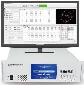
NSG8000
Select an expandable platform for receiver-development programs that may require additional signal licences, external motion integration or multiple independent RF outputs.
- Role in the Test Bench
- Generate selected GNSS RF signals from defined time, position and motion scenarios within the enabled configuration.
- Signal and RF Expansion
- Additional signal licences and independent RF-output hardware are configuration-dependent. Agree the initial scope and proposed expansion path before order.
- HIL and Project Interfaces
- For ordered real-time motion integration, confirm the interface, data fields, update behavior and defined latency measurement path against project requirements.
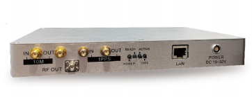
NSG2000
Select a compact platform for focused receiver development, debugging and firmware comparisons when the required signals and frequency points are defined before purchase.
- Role in the Test Bench
- Provide controlled civil GNSS inputs for repeatable receiver tests using the selected scenario and signal configuration.
- Fixed Purchased Frequency Configuration
- Confirm the required signals and frequency points before order. The delivered frequency configuration is fixed after purchase.
- Optional Closed-Loop Functions
- Where real-time closed-loop testing is required, confirm the ordered option, control interface, update behavior and latency acceptance for the actual configuration.
Match the Platform to the Interruption Test
Confirm how the selected bench applies and verifies RF interruption and restoration at the DUT input. Retain advancing scenario truth, RF-event evidence and receiver logs so the same-epoch error and recovery criteria can be evaluated.
Define RF Outputs and Signal Resources Separately
Frequency points, simulated signal channels and physical RF outputs describe different resources. Specify whether DUTs share one scenario or require independent position and motion inputs, then confirm the corresponding hardware and signal configuration.
Platforms for Specialized Evaluation Workflows

NPT4000
Consider NPT4000 for terminal-evaluation programs that need defined test profiles, configured execution, device records and structured result output. Confirm the supported tests and required DUT access for the evaluation workflow.
Explore NPT4000 Evaluation Workflows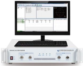
SGS8000
Consider SGS8000 for BeiDou RDSS terminal testing that requires outbound signal simulation, inbound response processing and short-message service verification. Review the terminal interface and complete RDSS workflow.
Explore SGS8000 RDSS TestingUse the scenario and test-bench configuration requirements to define the integration scope. For broader model selection, compare the GNSS simulation product family.
Implementation, Verification and Repeat-Test Handover
Commissioning and Deliverables
Establish the configured GNSS input, recording interfaces and reference comparison needed to repeat the agreed receiver tests. Define commissioning checks, evidence and responsibilities before execution. The technical and commercial proposal specifies the supplied equipment, licences, project files, engineering work, training and support.
From the Agreed Configuration to a Repeatable Test Workflow
For each applicable stage, agree the responsible team, completion conditions and records to include in the handover package.
Swipe or scroll horizontally to view all commissioning columns.
| Stage | Commissioning Checks | Record or Deliverable to Agree |
|---|---|---|
| 01 Agree Scope and Criteria | Confirm the DUT, signals, scenario time and route, starting-state procedure, RF architecture and required measurements. Define Cases A and B, observation windows and acceptance rules. | Versioned test plan with case IDs, limits, repeat count, timing and coordinate definitions, missing-evidence rules, equipment list and responsibility split. |
| 02 Verify Equipment and RF Path | Check the ordered platform, enabled signals and options, software versions, RF routing and DUT-port conditions. Verify applicable reference connections, control functions and receiver-recording interfaces. | As-built connection map, hardware and software identification, configuration record, RF-path checks and interface verification. Include calibration evidence where required by the agreed method. |
| 03 Qualify Baseline and Time Alignment | Check normal RF, truth continuity and recording coverage. Observe DUT baseline behavior. Establish epoch and coordinate mapping, and verify how event commands relate to E1/E2 at the DUT input. | Baseline records, truth provenance, frame and reference-point definitions, clock mapping and RF-event timing evidence, with relevant uncertainty and observation limits. |
| 04 Run the Paired Receiver Tests | Execute continuous-GNSS Case A and interruption Case B using the planned initial conditions. Verify RF events, keep scenario time and motion advancing, and observe the complete post-restoration verification window. | Case and run IDs, settings, E1/E2 records, raw DUT logs, truth data, aligned measurements and individual criterion results, including unavailable or incomplete evidence. |
| 05 Demonstrate Repeat Runs and Handover | Repeat the approved sequence using the agreed reset and retained-data procedure. Demonstrate configuration, recording, export and analysis steps. Review operator training and remaining actions within the project scope. | Versioned configuration and agreed scenario files, repeat-test procedure, delivered interface or analysis files, training records where included, and open-item owners and next actions. |
Prepare for Commissioning
- DUT Configuration and Data Access
- Prepare the DUT hardware and firmware, configuration access, output-message definitions and available diagnostics. Document initialization, retained navigation data and any assistance, corrections or sensor inputs used in the test.
- RF, Reference and Recording Resources
- Prepare the selected simulator, RF accessories, recording host and required references or instruments. Confirm access to truth, receiver logs and event evidence using the agreed test-bench configuration.
- Operators and Session Arrangements
- Agree the commissioning location, session format and responsible operators. For an included remote session, arrange a local operator with bench access and the required configuration and data-transfer arrangements.
Define the Handover Package
- Itemized Equipment and Licence Scope
- List the selected model, signals, frequency configuration, RF outputs, software and accessories. Classify each item as Included, Ordered Option, Project-Specific or Customer-Provided in the agreed proposal.
- Scenario and Integration Files
- Identify the agreed scenario files, settings, interface records and any control scripts or analysis files included in the project. Specify versions, formats, dependencies and responsibility for future changes.
- Verification Records, Procedures and Support
- Assign responsibility for RF checks, time alignment, required calibration and result analysis. Agree raw-record and report formats, repeat-test instructions, operator training and support coverage.
Practical Questions and Engineering Enquiries
GNSS Signal Simulation FAQ
Review the key questions about GNSS RF inputs, receiver observations, recovery and platform selection. Then share your DUT, required signals and test objective to request a configuration review.
What should I document before the first receiver test?
Record the test objective, scenario version, receiver starting state and the variable you intend to change. Agree on the pass criteria, observation window and repeat count before testing. See the receiver test setup.
When should I add a live-sky test or RF replay?
Use live-sky testing to check the receiver with its intended antenna and installation. Use RF replay when you need to reproduce a captured field event on the bench. See the comparison of simulation, RF replay and field testing.
How is recovery verified after a signal interruption?
Use verified normal RF restoration at the DUT input, E2, as the origin. Measure elapsed time to the start of the first interval meeting the required output states, freshness and error limits, then confirm the full verification duration. Record reacquisition and first accepted navigation output separately. Apply the recovery-window and evidence rules.
What DUT outputs and reference records are needed?
For position and continuity checks, define output epochs, positions, validity or mode fields, cadence and freshness. Retain aligned truth, RF-event records and recording coverage. Signal-state diagnostics are needed for the selected reacquisition criterion. Where required evidence is unavailable, mark that criterion Not Verified and identify the missing information.
How should I choose between NSG2000 and NSG8000?
NSG2000 suits compact receiver-test benches with a fixed purchased frequency configuration. NSG8000 suits programs needing an expandable signal scope or configured independent RF outputs. Both selections require review of the actual signals and interfaces. For NSG2000 closed-loop testing, confirm the ordered option and project requirements. Review the platform roles and configuration boundaries.
Can the simulator integrate with an external HIL system?
Review the selected model, HIL options and supported interface. Define motion fields, units, coordinate frames, timestamps, update behavior, error handling and the complete latency measurement path. Where system feedback is required, agree how it updates the motion model. See the GNSS HIL testing solution.
Are signal channels, frequency points and RF outputs the same?
Treat them as separate configuration resources. Required signals and frequency points define the GNSS coverage. Physical RF outputs define the bench input paths. Specify whether DUTs share one scenario or require independent position and motion states, then confirm the signal-channel allocation and ordered RF hardware.
How should the simulator be connected to the DUT?
Use the agreed conducted or appropriately shielded RF setup. Review connector and impedance compatibility, DUT input limits, path loss, antenna-bias/DC behavior and required conditioning. Verify the configured RF condition at the DUT input. Include output logging and reference connections in the test-bench integration plan.
Are scenarios, scripts, training and reports included?
The agreed technical and commercial proposal defines delivery. Identify the required scenario files, control or analysis files, verification records, report formats, training and support. Confirm included items, ordered options, project-specific work and customer-provided resources through the commissioning and deliverable scope.