
Multi-frequency GNSS
ANTGN-MF
All-system GNSS, multi-frequency.
- Antenna gain
- −2 to 2 dBi
- Supply voltage
- 3.3–16 V
- RF interface
- SMA
OEM components & receiver development
Compare three powered GNSS receiving antenna models for research, receiver development and OEM integration. Choose by signal coverage, supply voltage and RF interface, then request the configuration that fits your receiver.
Three model options
ANTGN-MF, ANTGN-CM and ANTGN-SF offer different system coverage and power requirements. The figures below are antenna gain values; LNA specifications are a separate part of receiver matching.
Multi-frequency GNSS
All-system GNSS, multi-frequency.
GNSS with L-band coverage
All-system GNSS + L-band.
GPS / BeiDou / Galileo
GPS, BeiDou and Galileo, multi-frequency.
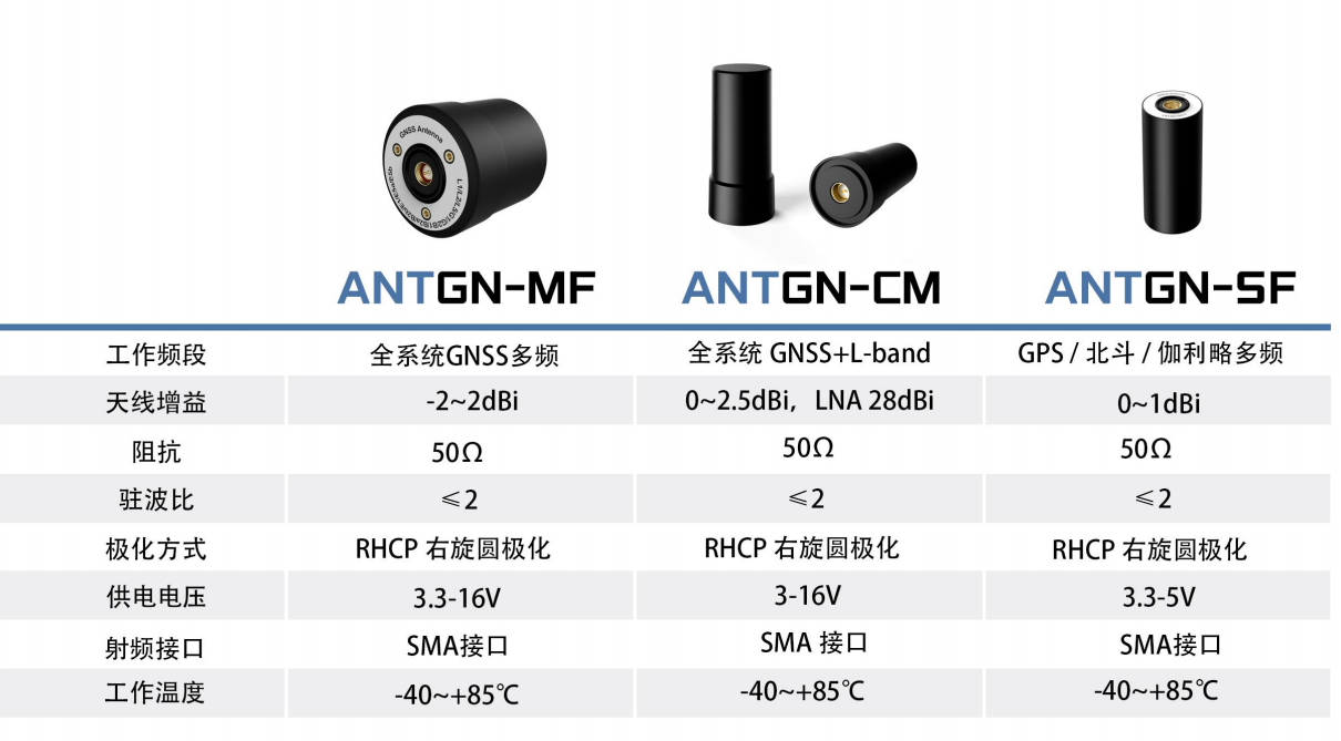
Product photos for model identification. The ANTGN-CM photo shows two views of the antenna.
Model comparison
Compare the electrical requirements first, then confirm the exact signal frequencies and mechanical connection for your configuration.
On smaller screens, scroll the table horizontally to see all specifications.
| Model | System / frequency description | Antenna gain | Supply voltage | Impedance | VSWR | Polarization | RF interface | Operating temperature |
|---|---|---|---|---|---|---|---|---|
| ANTGN-MF | All-system GNSS, multi-frequency |
−2 to 2 dBi | 3.3–16 V | 50 Ω | ≤ 2 | RHCP | SMA | −40°C to +85°C |
| ANTGN-CM | All-system GNSS + L-band |
0–2.5 dBi | 3–16 V | 50 Ω | ≤ 2 | RHCP | SMA | −40°C to +85°C |
| ANTGN-SF | GPS / BeiDou / Galileo, multi-frequency |
0–1 dBi | 3.3–5 V | 50 Ω | ≤ 2 | RHCP | SMA | −40°C to +85°C |
RHCP means right-hand circular polarization. System descriptions follow the supplied model data; an exact constellation and frequency list should be confirmed for the requested configuration.
Before requesting a configuration
Provide the receiver model and the GNSS systems and frequencies it needs to receive. For ANTGN-CM, specify whether L-band reception is required so the requested coverage can be checked.
Match the antenna supply range to the available power source. Include any receiver-provided antenna power, cable arrangement and current requirements. Request the LNA gain and noise specifications needed for your receiver design.
The listed RF interface is SMA. Confirm the exact connector type, mating details, cable length and mounting dimensions before ordering. Include a drawing or connector photo when the receiver interface is unclear.
It is the supplied coverage description for ANTGN-MF and ANTGN-CM. For a receiver project, request confirmation against your exact constellation and frequency requirements rather than treating the description as a complete signal list.
No. The published dBi values describe antenna gain. LNA gain describes amplification in the receiving electronics and should be checked separately, together with power and noise requirements. Include these requirements in your configuration request.
SMA identifies the interface family. Receiver fit also depends on the mating connector, supported signals, supply arrangement and mechanical installation. Send those details with the model and quantity you are considering.
Related Integration Guides
Use these guides to review the receiving architecture, cable assembly and antenna power before requesting a model configuration. Match the exact bands, RF interfaces and electrical requirements to your receiver.
Compare receiving architectures, antenna-element performance, amplifier gain and noise requirements before matching an antenna to your receiver and installation.
Build separate RF-loss and DC-power budgets, then verify the complete feeder, accessories and loaded antenna supply against the receiver and antenna requirements.
On the contact form, select OEM Modules & Boards. Send the antenna model, receiver or target equipment, required systems and frequencies, available supply voltage, RF connection and quantity to request a configuration quotation.