
GNSS Test Method Selection
GNSS Record & Replay vs Simulation vs Field Testing: Which Method Should You Use?
Choose GNSS RF record and replay to repeat a captured signal input, GNSS RF simulation to construct and vary supported test conditions, and field testing to evaluate the installed system in its operating environment. The right choice depends on the question and the evidence required.
These methods can work together. A field incident can become a replay case, a controlled simulation can test a suspected mechanism, and a return to the field can check the integrated fix. Start with the comparison below, or explore the GNSS Simulation 101 hub.
GNSS Record and Playback vs Simulation vs Field Testing
Compare the source of the stimulus, the variables you can change and the system boundary you actually exercise. Repeatability describes how well an input can be repeated; controllability describes which parts can be varied independently.
| Comparison | RF record & replay | GNSS RF simulation | Field testing |
|---|---|---|---|
| Input source | Previously captured signal samples reconstructed as RF. | RF generated from a configured scenario. | Signals received by the actual field installation. |
| Best initial use | Repeat a captured event or route for receiver comparisons. | Construct a baseline, vary parameters and test defined boundaries. | Discover operating issues and assess installed-system behavior. |
| What remains fixed | Captured geometry, motion and composite propagation within the recording. | Conditions explicitly held by the scenario and supported models. | Some route/procedure controls; sky and environment can change. |
| What can change | DUT, firmware and supported playback settings. Ordinary replay cannot independently edit every embedded effect. | Supported signals, motion, power, visibility and error-model parameters. | Route, installation, speed and operating procedure, within practical limits. |
| Reference truth | Independent, time-aligned truth from the original capture. | Scenario truth, validated against the intended reference point and model. | Surveyed or independently measured reference with stated uncertainty. |
| Antenna coverage | Capture-antenna effects are embedded. Conducted replay bypasses the replay DUT antenna. | Depends on conducted versus spatially appropriate OTA architecture. | Exercises the installed antenna, platform and local environment. |
| Real-time closed loop | A fixed recording does not respond to a new DUT-driven path. | Possible with the required motion interface, models and timing configuration. | Possible in the physical system, with less control of external conditions. |
| Main limitation | Evidence is bounded by what was captured and how it is replayed. | Evidence is bounded by model coverage, fidelity and configuration. | Exact input repetition and cause isolation are more difficult. |
Both replay and simulation can support regression. Neither guarantees identical DUT outputs across runs; preparation, oscillator state, internal noise, scheduling and measurement uncertainty still matter.
How Each GNSS Testing Method Works
RF record and replay: reuse a captured input
A recorder samples the signal passing through a defined antenna and RF chain within selected bands. Playback reconstructs those samples as RF for a receiver. The dataset can retain composite fades, multipath and interference that passed through the capture system, subject to its bandwidth, gain, quantization and continuity.
The recording is a reusable stimulus, not a guarantee that a field failure will recur. See the GNSS RF recording and playback workflow for capture, verification and replay responsibilities.
GNSS RF simulation: generate a defined scenario
A simulator computes RF signals from scenario settings and supported models. Engineers can construct nominal and stressed cases, vary a selected factor, use known scenario truth and supply real-time motion where supported. The model must represent the mechanism being investigated.
Real-time RF simulation delivers the stimulus in step with the bench timeline; closed-loop use also requires timely response to state updates. It does not mean live-sky reception. Use GNSS simulation fundamentals and the scenario design guide to define the inputs.
Field testing: exercise the installed system
Field tests include the installed antenna, housing, vehicle or platform, onboard electronics and operating procedures. They can reveal interactions outside a laboratory model. Satellite geometry, propagation and local activity may differ between runs, so use documented routes, environmental observations and suitable references.
Field A/B comparisons can be designed usefully, including simultaneous observations where practical. Document installation differences and changing conditions rather than assuming two trips present the same input. GPS.gov describes several real-world influences on user accuracy.[5]
RF Samples Are Different from Receiver Logs and Route Files
| Recorded data | What it represents | What replay can exercise |
|---|---|---|
| RF/IF waveform samples | A sampled representation of selected received bands, often using complex I/Q data, with acquisition metadata. | A compatible RF reconstruction path can stimulate the receiver front end, acquisition, tracking and navigation processing. |
| Receiver observations / RINEX observation files | Receiver-derived pseudorange, carrier phase, Doppler and related observations, as available. | Observation-domain estimation and analysis. These files are not the original sampled waveform. |
| NMEA / PVT / trajectory | Estimated position, time, status or a motion description. | Application playback or input to a generated scenario. A route log does not itself retain the original RF multipath or noise realization. |
Terminology varies. Safran’s GSG documentation, for example, describes a “Record and Playback” option that converts recorded NMEA messages into generated scenario, trajectory and event files.[4] Confirm whether a proposed workflow replays sampled RF or regenerates signals from logged information.
For sample-data exchange, retain the format, sample rate, center frequency, real/complex representation, quantization, packing, byte order and time mapping. The ION GNSS SDR Metadata Standard provides a framework for describing sampled signal data; format compatibility with the chosen playback equipment still needs confirmation.[1]
An estimated route can also contain receiver errors and latency. Validate it before using it as scenario truth. The GNSS receiver processing guide explains how observations and PVT are produced.
What Does a GNSS Recording Preserve—and Where Are Its Limits?
RF replay preserves the captured representation, not every physical condition around the vehicle. Qualify the capture chain before relying on a dataset.
| Boundary | Check | Consequence if missed |
|---|---|---|
| Bands and bandwidth | Required signals, center frequencies, usable bandwidth, filters and simultaneous capture combinations. | Uncaptured bands or filtered spectral content cannot be recovered by ordinary playback. |
| Gain and dynamic range | Antenna/LNA gain, recorder AGC or fixed-gain mode, overload and clipping indicators. | Compression can distort the desired signal and strong interferers. |
| Sampling and quantization | Sample rates, stored I/Q precision, packing and supported replay format. | Reduced representation or format errors can change the reconstructed input. |
| Continuity and references | Dropped samples, sustained storage throughput, clock/reference settings and event timestamps. | Sample gaps or time/frequency errors can create bench artifacts. |
| Antenna paths | Number of capture antennas, synchronized paths, relative delay and phase requirements. | One antenna recording cannot supply the missing spatial observations of a multi-antenna receiver. |
| Non-RF context | Truth, DUT logs, corrections, aiding, IMU/odometry, event markers and timestamp mapping. | The original receiver state or system interaction may be absent from replay. |
I/Q precision and quantization are capture-design choices, not simply file-size settings.[2] Keysight’s recorder documentation also illustrates the roles of gain records, dynamic range and replay-level controls. Those implementation details do not establish the capabilities of another product.[3]
Changing playback power does not independently change every signal
Ordinary gain or attenuation applied to a composite recording scales its recorded signal, noise and interference components together. Additional bench and receiver noise also affects the result. Do not assume a 1 dB playback change produces exactly a 1 dB change in receiver-reported C/N₀, or that it independently edits one satellite’s power. Verify the delivered input and observed receiver response.
Conducted replay and OTA test different boundaries
The capture antenna’s response is embedded in the recording. Connecting the replay output to a DUT RF port bypasses that DUT’s present antenna and its surroundings. OTA testing can include an antenna, but its spatial, polarization and multipath coverage depends on the chamber and radiating architecture. Do not assume a single radiating source recreates the original multi-direction field.[6]
Check storage rate as well as capacity
For N equal-rate complex streams with b bits for each I and Q component, the uncompressed sample payload rate is:
R = N × sample rate × (2 × b) ÷ 8 bytes/second
Illustrative calculation: two streams at 25 million complex samples/second, with 8-bit I and 8-bit Q, produce 100 MB/s and 180 GB in 30 minutes, using decimal units. This excludes headers, padding and auxiliary data; actual formats, compression and packing change storage needs. These values are not SSR8000 or MZ product specifications.
Why Might the Same RF File Fail to Reproduce a Field Issue?
A negative replay result does not prove the field report was wrong. Check the experiment before drawing a receiver conclusion.
- Missing input: the relevant band, antenna path, correction stream or inertial input was not captured.
- Capture damage: clipping, unsuitable quantization, a clock problem or sample gaps changed the stimulus.
- Different RF delivery: gain mode, cable loss, attenuation, noise or receiver input configuration differs.
- Different DUT state: firmware, retained navigation data, reset method, filter state or assistance differs.
- Insufficient lead-in: starting just before the event does not recreate the receiver’s earlier acquisition and filter history.
- Epoch mismatch: recorded GNSS time conflicts with current assistance, corrections or time assumptions.
- Different system boundary: power, thermal, antenna, platform or application behavior caused or contributed to the field failure.
Use the original recording epoch when aligning truth and supporting streams. Keep archived correction data synchronized and valid for that epoch, or deliberately define an unaided test. Check segment and loop boundaries rather than assuming continuous time and motion.
Once the bench input is validated, a repeatable failure shows that the tested input and DUT conditions are sufficient to reproduce the observed behavior. It does not, by itself, identify a unique physical cause.
Choose the Method by the Engineering Question
| Question | Useful starting method | What to add |
|---|---|---|
| Can we reproduce an archived RF incident? | Replay the verified capture with matched DUT preparation and supporting inputs. | Simulation for suspected mechanisms; field checks for omitted installation effects. |
| Did firmware B improve recovery? | Matched simulation cases and/or representative replay datasets. | Repeated trials, frozen scoring and structured field confirmation. |
| What is the response to a defined fault or power profile? | Simulation with the required calibrated controls and supported fault model. | Representative captured cases and the procedure required by the project. |
| Does an antenna or installation change help? | Installed-system field testing or a suitable antenna/OTA test architecture. | References and matched procedures; conducted receiver tests for separate electronics questions. |
| Must RF follow a controller-driven trajectory? | Real-time simulation with the required closed-loop interfaces and timing. | Actual-loop timing evidence and synchronized non-GNSS inputs. |
| What should production acceptance use? | A validated, repeatable stimulus and fixture selected for the required coverage. | Calibration, throughput checks, DUT preparation and traceable pass/fail criteria. |
Requirements or applicable procedures may prescribe a particular setup. Method selection alone does not establish certification or compliance. Use the receiver validation test plan to connect the requirement, test case and evidence.
A Practical Field-to-Lab Validation Example
Suppose a vehicle loses a valid GNSS solution near a building at t=420 seconds in a 900-second drive. The following is an illustrative investigation workflow, not a measured customer case.
- Field discovery: preserve the RF capture, DUT outputs, event interval, installation details and independent truth. Retain correction and inertial streams if the system uses them.
- Capture validation: verify required bands, sample continuity, overload status, metadata and the mapping between RF time and logs.
- Replay comparison: start A/B runs from the same declared capture point with sufficient lead-in and matched preparation. Compare the event using frozen validity and error rules; retain unsuccessful reproductions too.
- Controlled hypotheses: use simulation to vary suspected masking, multipath or interruption conditions separately. A simulated match supports a mechanism under the model; additional evidence is needed to attribute the field cause.
- Regression and field confirmation: retain the useful capture and simulation cases, then test the revised installed system on representative routes.
This sequence can run in either direction. A development program may establish simulation baselines before field discovery. The important link is traceability between the field observation, the replay dataset, the controlled hypothesis and the final decision.
Keep the Measurement Method Consistent
Define receiver initialization, accepted solution modes, truth, timestamps, event windows and failure handling before comparing results. Use the same metric definitions across methods while stating differences in conditions and measurement uncertainty.
For replay accuracy, compare the receiver’s reconstructed route with truth from the original capture interval, not the physical location of the laboratory bench. A DUT’s own position log is an output under evaluation, not independent truth. Repeating one recording measures behavior conditional on that captured input; those repeats are not independent samples of different field environments.
Separate first tracking return, first valid PVT and recovery meeting an accuracy or dwell requirement. Retain timeouts, missing outputs and failed preconditions alongside successful trials. Report error distributions and threshold availability where relevant, rather than only averages. The GNSS accuracy metrics guide defines the main quantities.
Match the Test Method to the Right System
Use the test boundary to choose a product family. Confirm current signals, RF architecture, interfaces, models and data formats against the project brief.
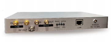
NSG2000
Consider for focused civil-signal receiver development, debugging and portable bench workflows. Confirm the required signals, trajectory method, models and integration options.
Review NSG2000 →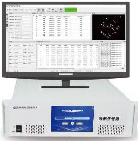
NSG8000
Consider for broader multi-constellation/frequency scenarios and advanced HIL architectures. Confirm independent RF views, timing requirements and optional functions for the selected configuration.
Review NSG8000 →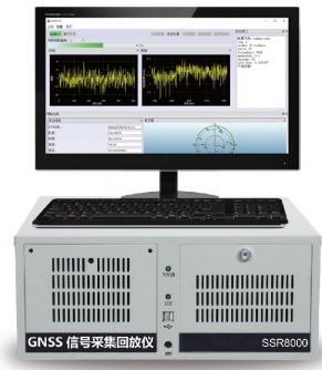
SSR8000
Consider for laboratory acquisition, stored RF datasets and replay-based receiver regression. Confirm simultaneous bands, sampling, storage, replay levels and reference interfaces.
Review SSR8000 →For portable route capture, compare MZ302P for a single antenna path with MZ303P for two synchronized antenna paths. Timing synchronization alone does not establish the relative-phase performance needed by every heading or array test; confirm the intended multi-antenna measurement.[6]
Explore the recording and playback product family, GNSS simulation systems and simulator selection guide. For integration planning, use the receiver development and HIL solution.
What to Confirm Before Selecting a Test System
For recording and replay
Provide the event or route objective; DUT and firmware; exact signals; antenna paths; required bands and usable bandwidth; expected duration; and supporting data. Confirm sample format and precision, gain/dynamic-range requirements, sustained storage rate, capture integrity indicators, replay compatibility, RF levels and timing references.
Include initialization and lead-in needs, historical epoch handling, independent truth and synchronized corrections or sensors. State which inputs must be replayed and which system functions remain live.
For generated simulation
Provide the exact signal set, scenario epoch, motion source, required models and deliberate parameter changes. Specify independent RF views, DUT connections, truth/logging and automation. For HIL, add protocol, coordinate frame, units, timestamps, update cadence, timing target and late-input policy.
For field confirmation
Define representative routes and operating conditions, installed hardware, reference quality, event logging, repeat procedure and how weather, sky visibility, traffic or platform changes will be recorded. Set the acceptance basis before reviewing results.
GNSS Record, Replay and Simulation FAQs
Is GNSS record and playback the same as GPS replay?
GPS replay usually refers to recorded GPS signal playback; GNSS replay may include other constellations and bands. Confirm whether the system replays sampled RF or regenerates signals from logged positions, and check the supported simultaneous signal coverage.
Can I change the route or remove one satellite after RF capture?
Ordinary waveform replay retains the captured composite. Some systems support playback-level or channel controls, but that does not imply arbitrary per-satellite or trajectory editing. Use generated simulation when those variables need independent control.
Does recording NMEA preserve the original multipath environment?
No. NMEA contains derived outputs and status, not the original RF waveform. It can help generate a scenario or replay an application route, but recreating multipath requires additional modeling or suitable RF-sample capture.
Can an RF recorder replay a complete HIL bench run?
RF samples cover the RF input. Replaying CAN, serial, corrections, IMU, controller states and other interfaces needs compatible synchronized recording and orchestration. A fixed RF replay also cannot follow a newly diverging closed-loop trajectory. Confirm each required interface separately.
Can record and replay replace field testing?
Replay can reduce repeated trips for an already captured input. The installed antenna, platform interactions, uncaptured environments and final operating workflow still require appropriate evidence. The amount of field testing depends on the requirement and the coverage of the laboratory setup.
Which method is best for GNSS regression testing?
Use controlled simulation for parameterized cases and verified recordings for representative captured events. Freeze input versions and scoring, control receiver preparation, repeat trials as planned and retain failed runs. Choose the mix that covers the actual requirements.
Do we need all three methods for every project?
No. A limited functional requirement may need a smaller test scope. Choose methods based on required coverage, uncertainty and the installed-system boundary. Complex navigation products commonly benefit from combining controlled bench tests with representative field evidence.
Choose the Method Before the Equipment
Send your DUT, test question, exact signals, antenna paths and intended evidence. Request a configuration review to discuss recording/replay, generated simulation or a combined workflow, including the interfaces and supporting data the test needs.
Technical References
Vendor documentation illustrates specific implementations. Confirm capabilities and interfaces for the selected test equipment.
- ION GNSS Software Defined Receiver Metadata Standard — sampled-data description and exchange.
- Racelogic: I/Q Signals and Quantisation — a legacy-platform explanation of sampling representation.
- Keysight GSS6450 Record and Playback System — capture gain, dynamic range, metadata and replay controls.
- Safran GSG: Record and Playback — an example of NMEA-to-generated-scenario terminology.
- GPS.gov: GPS Performance — signal-in-space and user-environment considerations.
- Safran: An Engineer’s Guide to CRPA Testing — spatial OTA and RF phase-alignment principles.
- GPS.gov: Interface Control Documents and Interface Specifications — GPS signal definitions.
- ESA Navipedia: Positioning Error — geometry and error concepts.
- Galileo Open Service: in-force reference documents; archived SIS ICD Issue 2.1 for tests tied to that earlier version.