
RF Components · Research & OEM Integration
RF Power Dividers & Splitters
P25 is a 2-way RF power divider for signal distribution in laboratory, research and OEM test equipment. Review its 0.5–6 GHz specifications, then confirm the RF signal levels, connector configuration and mechanical requirements for your equipment.
Available Component
P25 2-Way RF Power Divider
A connectorized RF distribution component with one COM port and two RF ports, marked RF1 and RF2. The model variant is P25-0.5G-6GHz.
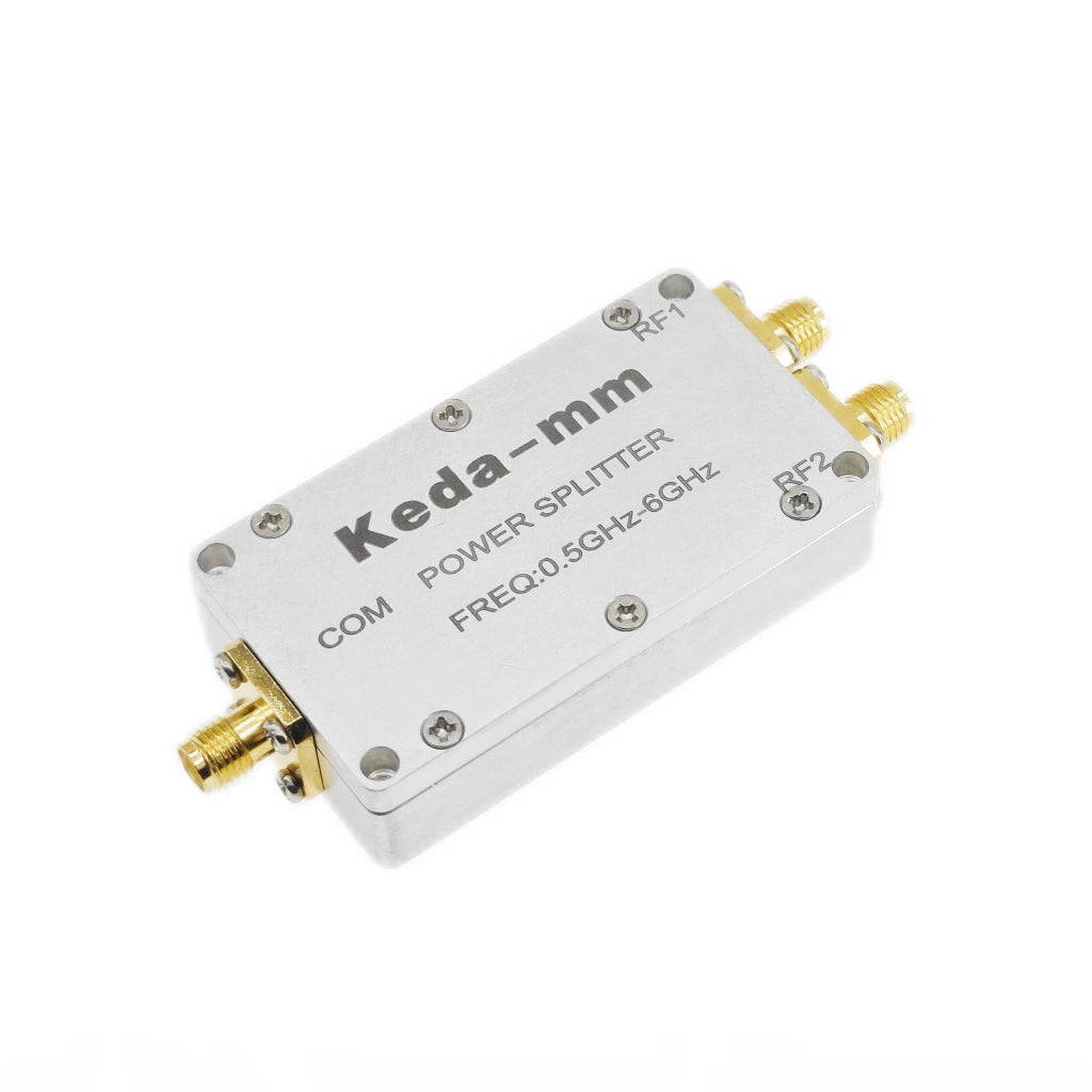
P25
P25 connectorized power divider. Confirm the supplied configuration and mechanical revision with your quotation.RF Signal Distribution
Compare the divider against your test requirements.
Evaluate the working band, distribution loss, output isolation and amplitude/phase balance for your laboratory or OEM test equipment. Review forward and reverse power ratings separately.
2-way divider0.5–6 GHz50 ΩSMA-K
Request the current model-specific datasheet and mechanical outline when preparing your order.
On smaller screens, scroll horizontally to read the specification conditions.
| Specification | Specification value | Conditions & confirmation |
|---|---|---|
| Operating frequency | 0.5–6 GHz | Operating frequency range. |
| System impedance | 50 Ω | RF system impedance. |
| RF interface | SMA-K | Confirm the supplied connector specification with the order. |
| Insertion loss, including distribution | 3 dB + <0.8 dB | 0.5–6 GHz; confirm the total path-loss definition and test conditions with the order. |
| Output isolation | 15 dB at 0.5–0.7 GHz 20 dB at 0.7–6 GHz | Confirm whether these levels are minimum or typical, and the applicable test conditions, with the order. |
| Input VSWR | <1.5:1 | 0.5–6 GHz; maximum VSWR specification. |
| Output VSWR | <1.35:1 | 0.5–6 GHz; maximum VSWR specification. |
| Amplitude balance | ≤0.3 dB | Confirm applicable test conditions with the order. |
| Phase balance | ±5° | Confirm applicable test conditions with the order. |
| Forward power capacity | 35 W average / 100 W peak | Forward RF power; confirm test conditions and derating. |
| Reverse power capacity | 2 W average / 30 W peak | Reverse RF power; confirm test conditions and derating. |
The loss specification includes a 3 dB distribution term; <0.8 dB alone is not the total path loss. Confirm the complete loss definition under your test conditions. Forward and reverse power ratings apply to different directions and do not establish an equivalent combining rating.
Selection & Integration
Confirm the RF and mechanical requirements.
Share the conditions that determine whether P25 fits your research or OEM test equipment.
Band and distribution requirements
Specify the working frequency and required loss, isolation, matching and amplitude/phase balance. Confirm the total path-loss definition and applicable test conditions against your acceptance criteria.
Direction and signal levels
State the intended signal direction and average/peak RF levels. Review the applicable forward or reverse rating, test conditions and derating for the proposed configuration.
Interfaces and supplied revision
Confirm the connector designation, mechanical outline, mounting envelope and delivery revision. Include the required quantity, destination and timeline; sample availability and lead time are confirmed with the quotation.
Selection FAQ
Questions before ordering P25.
What does the P25 2-way divider provide?
P25 is an RF signal distribution component for laboratory, research and OEM test equipment. P25 has one COM port and two RF ports, RF1 and RF2. Its operating range is 0.5–6 GHz in a 50 Ω RF system.
Is the total insertion loss less than 0.8 dB?
The loss specification is 3 dB + <0.8 dB, including distribution. The <0.8 dB figure should not be used alone as a total path-loss specification. Confirm the complete loss definition and test conditions before setting acceptance limits.
Do the forward and reverse power ratings mean the same thing?
The forward capacity is 35 W average / 100 W peak; the reverse capacity is 2 W average / 30 W peak. Keep these ratings separate. They do not establish equal power handling in both directions or an equivalent combining rating; confirm the intended use and test conditions with the quotation.
What should I include in a P25 inquiry?
Include the model, operating band, RF signal direction and average/peak levels, connector and mechanical requirements, quantity, destination and timeline. Request the current datasheet and outline for the supplied revision. Sample availability, price and lead time are confirmed for the proposed order.
OEM Component Procurement
Request P25 specifications or a quotation.
On Contact, select OEM Modules & Boards. Include P25, the working frequency, RF signal direction and average/peak levels, connector and mechanical requirements, quantity, destination and timeline so we can review the appropriate supplied configuration.