
GNSS Receiver Resilience Testing
GNSS Spoofing & Interference Testing
Evaluate how receivers detect abnormal GNSS inputs, handle affected navigation or timing outputs, and recover after controlled test events. Compare normal baseline, event and recovery phases using time-aligned DUT observations and appropriate reference data, with RF conditions and acceptance criteria defined for your application.
For authorized testing in conducted or appropriately shielded laboratory setups.
Principle, RF Inputs and Test Evidence
How GNSS Spoofing and Interference Testing Works
GNSS resilience testing combines a defined normal signal environment with a selected spoofing or interference stimulus. Receiver outputs are evaluated against the normal reference and recorded event times across baseline, event and recovery phases. Detection, output correctness and recovery are assessed as separate observations.
Evaluate Misleading Navigation Inputs
Controlled GNSS-like signals can cause erroneous position or time results while receiver tracking continues. Evaluate the response by examining error relative to the normal reference, available alarms, and output-validity or mode changes.
Evaluate Degraded GNSS Reception
Defined unwanted RF energy can degrade GNSS acquisition and tracking. Evaluate remaining usable outputs, diagnostic status, available alarms and recovery after restoring the normal condition. Output behavior depends on the DUT and test settings.
Connect the RF Test Path to the Measurement Evidence
Select the source role for each test case, verify the RF condition delivered to the DUT, and align its observations with suitable reference data and verified stimulus-event records. PVT means position, velocity and time.
Provides the defined normal GNSS scenario and reference signal environment.
Provides the selected spoofing or interference stimulus for the test case.
Route and condition the sources to establish the defined RF input at the DUT.
Exercise the receiver in its selected operating state.
Collect available PVT, tracking, alarm, timing and status outputs.
Additional Inputs to Evaluation
Supply normal-scenario truth or suitable independent reference data.
Supply stimulus start and end records with timestamp alignment evidence.
Align all three evidence inputs and compare the measured response with agreed criteria.
Establish the Starting Condition
Verify the normal signal environment and selected receiver state. Record baseline error, output status, tracking and available alarms before introducing the test event.
Observe Detection and Output Behavior
Confirm the applied event and align its records with DUT observations. Evaluate error, available alarms, usable outputs and mode changes against the agreed event-phase requirements.
Verify Return to Accepted Operation
Restore the defined normal RF condition and observe the DUT. Confirm that selected outputs meet their requirements throughout the agreed verification window, alongside available reacquisition and relock records.
Two Test Cases, Separate Evidence
Example: Evaluating Receiver Response and Recovery
Evaluate a stationary civil GNSS navigation receiver in two separate test cases. The spoofing case examines detection and the handling of affected outputs. The interference case examines usable output, tracking degradation and recovery. Each run starts from a verified normal baseline.
Illustrative test design: the phase layout and record template describe a proposed method. Durations, stimulus settings, limits and DUT results are defined and recorded for the actual test. The timeline contains no measured performance results.
Single-Antenna Navigation Receiver
Use the same receiver hardware, firmware and settings. Define initialization, retained navigation data, assistance and auxiliary inputs. Confirm which PVT, status, tracking and alarm records are available.
Known Stationary Position
Use a normal GNSS scenario at a known fixed position. Define the coordinate frame and observation point. Align DUT outputs, normal-scenario truth and verified RF-event records to a common time basis.
Separate Runs with Controlled Conditions
Execute the two cases separately and restore the agreed starting state before each run. Set repetition counts in the test plan. Keep each case's conditions consistent when comparing receiver or firmware variants.
Align Each Run to Its Verified Event Window
Use the same phase definitions for both cases, with separate event timestamps and records for every run. The schematic widths below do not represent phase durations.
E1 and E2 identify the verified onset and end of the selected RF stimulus at the DUT input. Document how command or trigger times relate to those events. Record DUT alarms, tracking transitions and recovery separately.
Detection and Output Protection
Does the receiver identify the controlled condition, and how does it handle outputs that exceed the application's accepted error?
- 1. Establish the Normal Baseline
- Verify the position result against normal-scenario truth. Record output validity, receiver mode, tracking and available alarms. Confirm the baseline meets the starting requirements.
- 2. Execute the Approved Spoofing Case
- Retain E1, E2 and the source settings. Collect available alarms, reference-relative position error and output-state changes. Record intervals when error exceeds the agreed limit and the DUT continues to label the output as valid or usable.
- 3. Observe Recovery and Remaining Effects
- Restore the defined normal input and continue logging. Observe alarm clearing, mode transitions and reference-relative error. Identify any interval that satisfies the complete recovery verification requirement.
Decision focus: compare detection timing and handling of over-limit outputs with the receiver and application requirements. Evaluate alarm behavior and output correctness as separate criteria.
Tracking Degradation and Recovery
Which outputs remain usable during the controlled event, and when does the receiver return to accepted operation?
- 1. Verify Normal Reception
- Confirm the same baseline definition and agreed starting state. Record reference-relative position error, output status, tracking diagnostics and available interference indicators.
- 2. Execute the Approved Interference Case
- Retain E1, E2 and the verified RF conditions. Record tracking changes, output epochs and gaps, available alarms, output validity and position error. Apply the agreed application-usability rules to observed outputs.
- 3. Verify Post-Event Operation
- Restore the defined normal RF condition and continue observation. Record available reacquisition and relock events. Locate the start and completion of an interval in which selected outputs satisfy the recovery requirements.
Decision focus: evaluate output usability during the event and recovery against the agreed limits and verification duration. Retain reacquisition and relock as separate observations.
Record Template for Each Test Run
Populate the records below from the actual test. Agree output fields, numerical limits, observation durations and missing-data rules before execution.
Swipe or scroll horizontally to view all columns.
| Record | Spoofing Case | Interference Case | Reporting Rule |
|---|---|---|---|
| Applied Event | Verified E1 and E2, source settings and DUT-input RF-event evidence. | Verified E1 and E2, source settings and DUT-input RF verification. | Retain the common time mapping and uncertainty of event alignment. |
| DUT State and Alarms | Available detection alarms, output-validity flags, receiver modes and tracking records. | Available interference indications, tracking transitions, output-validity flags and receiver modes. | Timestamp state changes and identify unavailable fields or incomplete evidence explicitly. |
| Position Error and Output Usability | Aligned position error and intervals of over-limit output, with the corresponding reported state. | Aligned position error, accepted outputs and observed output gaps during the event. | Use normal-scenario truth, the agreed reference point and usability rules. Preserve unassessable epochs. |
| Recovery Window | Reference-relative error and required output states throughout the selected verification interval. | Accepted outputs throughout the verification interval, alongside available reacquisition and relock records. | For this example, measure elapsed time from E2 to the start of the qualifying interval; confirm it at completion. |
| Criterion Results | Separate decisions for required detection, output handling and recovery. | Separate decisions for event-phase usability and recovery. | Report Pass, Fail or Not Verified with the method, limit and evidence. State whether the required observation window was completed. |
If no qualifying recovery interval is observed, report Not observed within the available interval and its duration. Apply the agreed decision rule for deadlines, incomplete observation and missing records.
Measured Response, Evidence Quality and Test Decisions
Measurements and Acceptance Criteria
Verify the applied RF condition, normal reference and time alignment before evaluating the DUT. Define each metric, numerical limit, observation window and missing-data rule in the test plan. Assess detection, output correctness, usability and recovery separately for each spoofing or interference case.
Define the Evidence and Acceptance Rule for Each Criterion
Swipe or scroll horizontally to view all measurement and acceptance columns.
| Metric or Check | Measurement Method | Acceptance Definition to Agree |
|---|---|---|
| Input Qualification Stimulus, Baseline and Event Timing | Verify the normal scenario, selected stimulus and RF condition at the DUT input. Retain E1/E2 event evidence, reference continuity and timestamp mapping. | Required signals and starting state, allowed RF deviations, event-definition and alignment uncertainty, and the conditions that qualify a run. |
| Detection Evidence Reported Alarm Latency and Baseline Alarms | Measure the selected alarm response from the verified test-condition onset. Count new unintended alarm episodes during qualified normal or control intervals. | Required alarm, clear starting state, timestamp observation point, response deadline, baseline-alarm rule and logging coverage. |
| Reference Comparison Position or Timing Error | Compare aligned position outputs with normal-scenario truth or suitable independent reference data. For timing DUTs, use the defined physical comparison reference and measurement chain. | Error type and units, sample set, maximum or statistical limits, reference point, time scale where applicable, and uncertainty treatment. |
| Output Handling Over-Limit Outputs and Reported State | Align measured error with output-validity flags, receiver modes and alarms. Identify over-limit outputs that remain declared valid or usable. | Required warning, validity, suppression or fallback behavior where specified; permitted transition intervals and output-handling limits. |
| Reception and Usability Tracking State and Usable Output | Retain available tracking diagnostics. Classify expected output epochs by agreed usability conditions, including measured error limits when required. | Required tracking observations, accepted modes, freshness, output cadence, minimum usable-output fraction and treatment of unknown states. |
| Post-Event Response Verified Recovery | Find the first interval after the selected origin that meets the required output conditions for the complete verification duration. | Timing origin, qualifying states and limits, verification duration, sampling and gap rules, and whether a deadline applies to interval start or completion. |
| Repeated Runs Case and Firmware Comparability | Retain per-run values, case settings, starting states, completed observations and exclusions. Compare variants using the same case definition. | Repetition count, allowed setup variation, aggregation method and the evidence needed for the stated comparison. |
Apply criterion-specific requirements: select the observations supported by the DUT and required by the application. Record unavailable evidence explicitly and keep conclusions tied to the tested case and configuration.
Measure Reported Alarm Latency
Specify the alarm and timestamp observation point. Confirm its required starting state and define what counts as a new assertion.
- tevent
- Verified onset of the defined RF test condition at the DUT input, such as E1.
- talarm
- First qualifying alarm assertion recorded at the stated observation point.
- Timing Quality
- Document clock mapping, resolution, polling and transport effects. Polled records may bound the assertion time.
Host receipt timestamps measure response through that interface. Label the measured latency accordingly. If no alarm is observed, report the observation interval and evidence coverage. Qualified monitoring through a required deadline can establish a failure; unavailable or incomplete evidence may leave the criterion Not Verified.
Calculate Error Against the Normal Reference
For horizontal position error, calculate East and North differences in a common frame, in metres, at matched epochs and the agreed reference point.
- Horizontal RMS
- Square root of the mean squared horizontal errors over the stated sample set.
- Selected Percentile
- Report the chosen percentile, calculation method, evaluated samples and unavailable epochs.
- Reference Quality
- Retain normal-scenario truth or independent reference data, coordinate mapping, epoch alignment and relevant offsets.
DOP and receiver uncertainty estimates are supporting diagnostics. Accuracy requires suitable reference evidence. For timing DUTs, separately define the measured output, relative or absolute timing objective, reference relationship, epoch, time scale, path-delay corrections and instrument uncertainty.
Classify Output Usability at Each Epoch
For a predefined window and fixed output cadence, classify every expected epoch once using agreed timestamp tolerances and freshness rules.
- U / Usable
- Observed output meets the selected state, freshness and any required measured-error limits.
- F / Unusable
- Available evidence confirms an unusable output or confirmed absence of required output.
- Q / Unknown
- Missing or unusable output or reference records prevent a supported usability decision.
For N > 0, these percentage bounds preserve unresolved states. With complete evidence they coincide. Retain the denominator, exclusions and decision rule. Variable-rate outputs need a separately defined time-based method.
Correlate Error, Output State and Alarms
Match measured error, reported output state and available alarms at the same epochs. Report confirmed over-limit outputs alongside their declared state, including outputs that remain marked valid.
Record episode counts and supported durations under a stated sampling or interpolation rule. Keep unknown intervals visible. Retain all outputs claimed usable in the applicable evaluation, including over-limit samples.
For qualified normal or control intervals, count new unintended alarm episodes using a stated assertion, latching and clearing rule. Report monitored duration and logging coverage with any alarm rate. Alarm behavior and output handling have separate acceptance criteria.
Confirm Recovery Over the Complete Verification Window
In the two-case example, use E2, the verified stimulus end, as the timing origin. Find the first interval beginning at or after E2 that satisfies the selected output states, freshness and error limits for the full agreed verification duration, with the required measurement cadence and gap rules.
Measure elapsed time to the start of the qualifying interval and confirm it at completion. Record both timestamps and the applicable deadline. Measured violations restart verification; unresolved gaps may prevent confirmation. Retain reacquisition and relock separately. If no complete qualifying interval is observed, state the available duration and whether the required acceptance observation was completed.
When the required output condition remains satisfied through the event, report continuous compliance or no recovery required according to the test plan.
Pass
The setup and evidence qualify the measurement, and the result meets the criterion under its agreed limits, uncertainty treatment and observation rules.
Fail
Qualified evidence establishes a violated limit or required behavior, including a required response absent through a completely observed deadline.
Not Verified
Missing reference data, unavailable outputs, unresolved records, insufficient observation or an unqualified setup prevents a supported decision.
Sources, Interfaces and Integration Scope
Test Bench Configuration and Integration
Configure the bench around the receiver architecture, normal GNSS environment, selected test case and required measurements. Confirm source roles, RF connections, timing, data access and equipment responsibilities before integration. Document the supported functions and project-specific work in the agreed configuration.
Define the GNSS Reference
Specify the normal civil GNSS signals, scenario position or motion, time scale and epoch. Identify the source providing this environment and retain the normal reference needed for output-error evaluation.
Define the Test Source Role
Select the spoofing or interference source for each case. Confirm supported signals, operating modes and coordination requirements. Review any combined-case architecture and its evidence requirements separately.
Define the Measurement Chain
Confirm available DUT outputs, reference data and event records. Include suitable physical references and instruments when required for timing measurements, with a documented alignment to the test timeline.
Confirm Each Connection and Its Function
Complete the connection plan using the actual source, DUT and instrument specifications. Identify the purpose, direction and required evidence for each configured interface.
Swipe or scroll horizontally to view all columns.
| Connection or Role | Signal and Purpose | Requirements to Confirm | Configuration Record |
|---|---|---|---|
| Normal GNSS Source → RF Test Path | Normal signal environment for baseline, event and recovery observations. | Selected civil signals, scenario definition, source compatibility, continuity and normal-truth data. | Scenario version, signal settings, time definition and reference records. |
| Test Source → RF Test Path | Selected spoofing or interference stimulus for the approved case. | Supported case and bands, source operating states, RF routing and coordination with the normal source. | Case definition, source settings and verified E1/E2 event evidence. |
| RF Test Path → DUT Input | Defined RF input through the selected routing and signal-conditioning arrangement. | Connector and impedance, DUT-port level after path loss, antenna DC handling, source isolation or protection, and contained routing. | As-built RF map, input-level verification, path loss and DC arrangements. |
| Reference and Trigger Connections | Frequency, pulse or event synchronization where provided by the selected equipment. | Actual input/output roles, supported levels and termination, reference-lock state, trigger meaning and relation to scenario time. | Port directions, clock routing, epoch definition and alignment evidence. |
| DUT → Logging Host | Available PVT, validity, tracking, mode and alarm observations. | Supported interface or export method, message fields, output cadence, timestamps, freshness and missing-record indicators. | Interface settings, data formats, field definitions and logging configuration. |
| Reference and Instruments → Test Record | Normal truth or independent measurements for the selected error criteria. | Reference point, coordinate or time scale, measurement cadence, units, relevant corrections and uncertainty. | Reference provenance, instrument settings, correction records and data mapping. |
| Controller → Sources, Where Supported | External commands and status collection for the agreed test sequence. | Supported protocol and command set, software versions, state reporting, timing behavior and agreed error handling. | Control-interface definition, sequence version and command-to-event mapping. |
Document synchronization by function: frequency-reference sharing, second-boundary alignment and GNSS scenario epoch are separate requirements. Confirm the supported port direction and role for each device in the actual bench.
Define Repeatable Operating Conditions
- Receiver State and Auxiliary Inputs
- Record DUT hardware, firmware, settings and initialization. Define retained navigation data, assistance, corrections and sensor inputs where used. Confirm their interfaces and timing separately from the GNSS RF path.
- Scenario and Event Sequence
- Define baseline, event and recovery phases for each case. Retain the normal scenario, E1/E2 definitions, normal-condition restoration and any planned resets. Keep intentionally changed conditions visible in comparisons.
- Measurements and Acceptance Records
- Specify output fields, time mapping, numerical limits, observation and verification windows, logging coverage and missing-data rules using the agreed measurements and acceptance criteria.
Confirm the Supported Project Scope
- Control and Automation
- Review the available command documentation, protocols, software versions and data formats. Define requested sequence control, logging, alignment and reporting work within the agreed scope.
- Feedback-Controlled Workflows
- Where feedback is required, define DUT input fields, units, coordinate frame, timestamps, update rate and latency requirements. Confirm source support and an acceptance method for the complete update path.
- Multi-Antenna and CRPA Requirements
- Provide RF-input or antenna-element mapping, phase and amplitude requirements, and the required calibration evidence for feasibility review. Specify these requirements alongside RF channel count.
- Supplied and Customer-Provided Equipment
- Identify selected sources, normal references, RF accessories, instruments, data hosts and software. Agree which items are supplied and who performs integration, calibration and verification.
Spoofing Sources and Interference Test Sources
ASG and JSG Platforms in the Test Bench
Select the source by test objective, signal requirements and integration needs. Use the ASG series for controlled spoofing cases and JSG8000 for interference testing. Confirm the normal GNSS environment, RF architecture, timing and measurement chain for the complete bench.
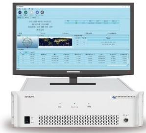
ASG8000
Choose a full-featured spoofing source for coordinated laboratory benches, receiver validation and external-control integration.
- Test Source Role
- Controlled spoofing generation for replay, generative and meaconing test cases in the selected configuration.
- Relevant Bench Functions
- External command control, control-interface integration, and 10 MHz, 1PPS and network timing outputs for coordinated workflows.
- Confirm for Your Test
- Required signals and case types, RF interfaces, source coordination, control protocol and any feedback-update requirements.
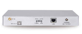
ASG2000
Choose a compact spoofing source for focused receiver validation, smaller laboratories and portable lab setups.
- Test Source Role
- Controlled replay and generative spoofing test cases within the selected signal configuration.
- Relevant Bench Functions
- Compact form factor, external command control, and 10 MHz, 1PPS and network timing outputs for bench coordination.
- Confirm for Your Test
- Required signal combination, RF input and output roles, synchronization, power arrangements and supported control functions.
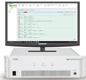
JSG8000
Choose an interference source for receiver anti-jamming evaluation, tracking-response observation and recovery testing.
- Variant and RF Channel Selection
- JSG8140 provides one independent RF channel; JSG8340 provides three independent RF channels.
- Relevant Bench Functions
- Configurable interference modes, synchronous triggering and an RJ45 control interface for the selected test workflow.
- Confirm for Your Test
- Required bands and modes, independent channel count, DUT-input RF conditions, trigger and reference roles, and control protocol.
Confirm Source Coordination and Antenna Architecture
For requested combined spoofing and interference cases, review source coordination, RF routing and event alignment together. Multi-antenna or CRPA testing also requires antenna-element mapping, phase and amplitude requirements, and suitable calibration evidence. Confirm feasibility for that architecture alongside RF channel count.
Agree the Complete Bench and Integration Scope
Include the normal GNSS source and truth, RF conditioning, DUT logging, and physical references or instruments required by the selected measurements. Identify supplied and customer-provided items. Define supported control functions and any agreed automation, data-alignment or reporting work.
Review the test-bench configuration requirements for connection and integration planning, or compare the spoofing and interference product family for model selection.
Implementation, Verification and Handover
Commissioning and Deliverables
Establish a verified test bench and a documented workflow for repeating the agreed receiver tests. Define source configuration, reference data, acceptance criteria and responsibilities before commissioning. Equipment, integration, records, training and support follow the agreed project scope.
From an Agreed Test Plan to a Repeatable Receiver Test
For each applicable stage, agree the checks, responsible team and records to be included in the handover package.
Swipe or scroll horizontally to view all columns.
| Stage | Commissioning Checks | Record or Deliverable to Agree |
|---|---|---|
| 01 Agree the Test Scope and Criteria | Confirm the DUT and antenna architecture, required signals, selected spoofing or interference cases, normal reference, DUT starting state, auxiliary inputs and evaluation rules. | Versioned test plan with case IDs, phase definitions, limits, verification windows, repeat counts and missing-evidence rules; equipment list and responsibility split. |
| 02 Verify Bench Connections and Functions | Check source roles, RF routing and DUT-input conditions in the agreed conducted or shielded bench. Verify reference and trigger directions, supported control functions, and DUT logging connections. | As-built connection map, hardware and software versions, source and interface settings, and applicable RF-path, reference and functional-verification records. |
| 03 Qualify the Baseline and Event Alignment | Verify normal DUT outputs, available alarms and log coverage. Align DUT and reference records. Establish how command or trigger timestamps relate to actual RF-stimulus onset and end at the DUT input, identified as E1 and E2. | Baseline results, normal-reference provenance, clock and event-time mapping, verification evidence and relevant uncertainty or observation limits. |
| 04 Execute the Agreed Receiver Tests | Run the selected cases with documented starting conditions and repetitions. Record receiver response, restore the defined normal input and observe the full recovery verification window. Evaluate each applicable criterion. | Case and run IDs, source settings, RF-event records, DUT logs, reference data, aligned measurements and criterion-by-criterion results, including evidence gaps. |
| 05 Handover the Repeat-Test Workflow | Demonstrate configuration, baseline checks, case execution, data export and the agreed analysis method. Review operator training, delivered integration files where included, and remaining actions. | Versioned settings, operating and test procedures, agreed training records, and open-item owners and next actions. |
Prepare for Joint Commissioning
- DUT, Equipment and Access
- Prepare the selected test sources, normal GNSS environment, RF conditioning and required instruments. Confirm DUT firmware, configuration access, output logs and the agreed starting-state procedure.
- Reference Data and Timing
- Prepare normal-scenario truth or suitable independent reference records. Where timing accuracy is evaluated, confirm the physical reference relationship, applicable path-delay corrections and measurement uncertainty.
- Operators and Session Format
- Agree the session format and responsible operators. For a remote session included in the project scope, arrange a local operator with equipment access and the required data-transfer arrangements.
Confirm the Project Package
- Supplied Items and Integration
- Itemize source configurations, software and accessories. Identify supplied and customer-provided equipment, supported interfaces, and any agreed control, logging or automation work.
- Verification and Data Package
- Assign responsibility for RF and reference checks, calibration, event alignment and result analysis. Agree raw-record and report formats. Define antenna-path calibration requirements for any agreed multi-antenna architecture.
- Procedures, Training and Support
- Agree configuration versions, repeat-test procedures, training coverage, support arrangements and the records of completed commissioning activities.
Practical Questions and Engineering Enquiries
GNSS Spoofing & Interference Testing FAQ
Review the key questions about test inputs, receiver observations, recovery and integration. Then share your receiver, required signals and test objective to request a configuration review.
How do spoofing and interference tests differ?
Spoofing tests use controlled GNSS-like inputs to evaluate misleading position or time solutions and receiver detection. Interference tests use unwanted RF energy to evaluate degraded acquisition, tracking and usable outputs. Select ASG sources for the agreed spoofing cases and JSG8000 for interference testing. See the test principle and measurement chain.
Does a valid fix or an alarm prove acceptable performance?
A receiver may continue tracking and reporting a valid solution while its position or time is incorrect. Evaluate measured error, output usability, available alarms and operating modes against their respective criteria. Report detection and affected-output handling separately, using records aligned to the normal reference.
Do I need a normal GNSS source and reference data?
Define the normal GNSS input for baseline and recovery checks. Evaluate position or velocity error using normal-scenario truth or suitable independent reference data, aligned by epoch, coordinate frame and observation point. Timing accuracy also requires an appropriate physical reference relationship and applicable path-delay treatment. Agree which items are supplied or customer-provided.
Can spoofing and interference be tested together?
Review combined-case feasibility for the selected sources, signals, RF architecture and event alignment. Define how each stimulus will be verified at the DUT input and which receiver responses will be assessed. Agree source coordination and integration scope, with separate case records for individual and combined tests where included in the plan.
How are alarm latency and recovery measured?
Measure reported alarm latency from verified RF-event onset at the DUT input to the qualifying alarm assertion at the stated observation point. Document clock mapping and interface effects. Measure recovery from verified stimulus end to the start of a qualifying interval, confirmed only after its full duration. Evaluate reacquisition and relock separately. See the measurement definitions and recovery rules.
Can these sources be used for multi-antenna or CRPA tests?
Review antenna-element mapping, RF routing, required phase and amplitude relationships, synchronization and calibration evidence. Independent RF channel count is one selection input; feasibility for the complete antenna architecture must also be established. Include the DUT, antenna arrangement and required observations in the test-bench configuration review.
What if the receiver exposes limited logs, or I need automation?
Select measurements supported by available DUT outputs and reference data. Where required evidence is unavailable, report the affected criterion as Not Verified. For automation, agree supported protocols, commands, data formats, timestamp mapping and responsibilities. Define any requested DUT-feedback update path and its acceptance requirements separately.
Which acceptance limits and deliverables should we specify?
Choose application-specific limits for each test phase, plus observation windows, sampling and missing-evidence rules. Agree the records needed to repeat the test and support each decision. Hardware, integration, procedures, training and support follow the project scope. Review the commissioning stages and deliverables.