
RF Components · Research & OEM Integration
RF Switch Components
RF switching components for laboratory signal routing, test hardware and OEM integration. Compare KDA01-DC-20SPDT and SW-SSP-20G by switching topology and RF characteristics, then confirm the control, supply and mechanical requirements for your equipment.
Component Comparison
Select the required RF switching topology.
KDA01-DC-20SPDT is an SPDT RF switch component; SW-SSP-20G is an SPST RF switch module. Product views show reference configurations. Confirm the supplied form, interfaces and revision with the quotation.
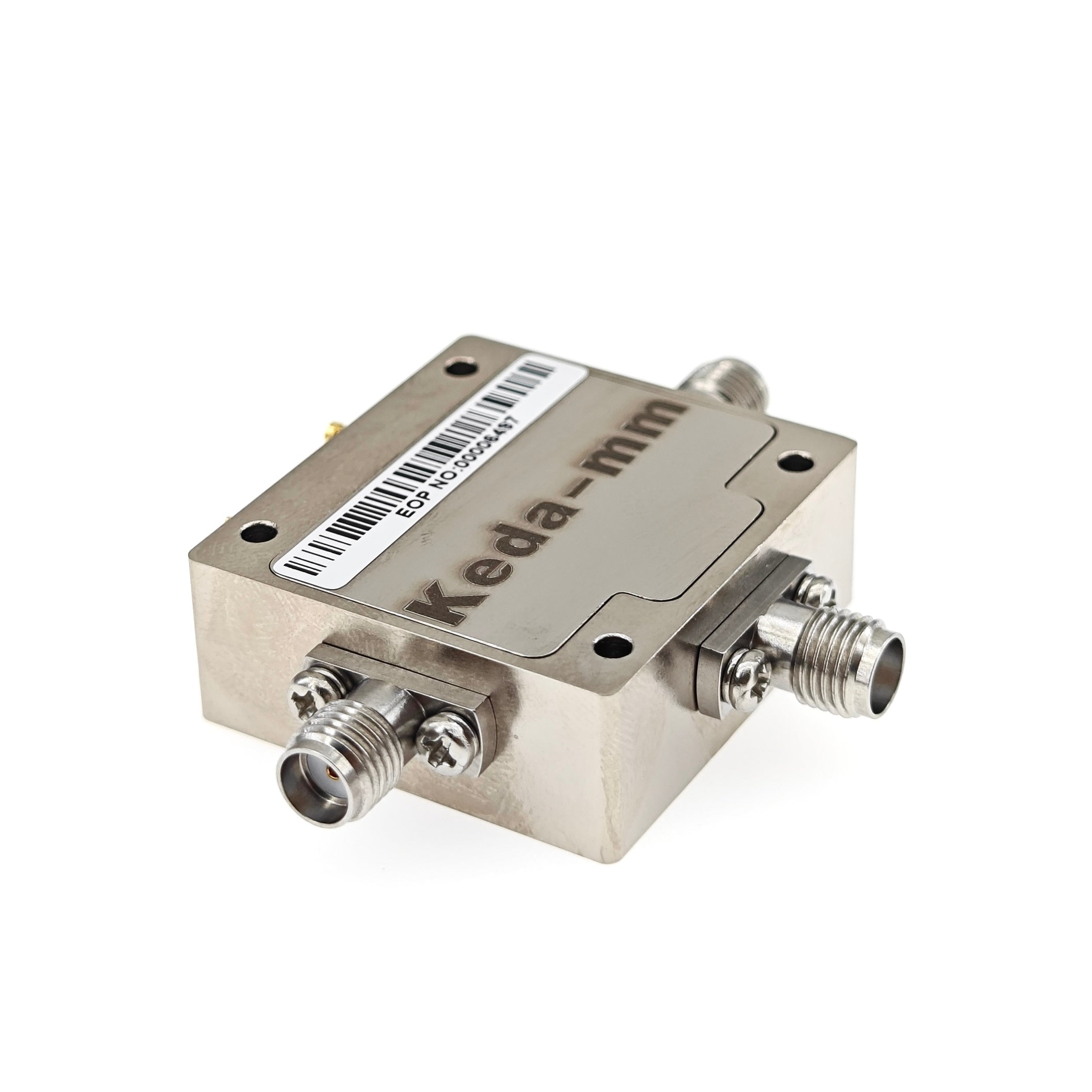
KDA01-DC-20SPDT
SPDT switch component. Connectorized reference configuration; confirm supplied form.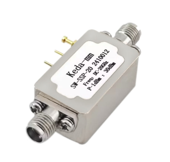
SW-SSP-20G
SPST switch module. Product reference view.On smaller screens, scroll horizontally to compare both components.
| Specification | KDA01-DC-20SPDT | SW-SSP-20G |
|---|---|---|
| Switching topology | SPDT | SPST |
| Frequency range | DC–20 GHz | DC–20 GHz |
| Insertion loss | 4 dB typical @ 20 GHz | 1.3 dB typical @ 20 GHz |
| Switching time | 20 ns typical | 20 ns (reference figure) |
| Bias reference | −5 V | −5 V |
| Bias current | 1.2 mA typical @ −5 V | 1.2 mA typical @ −5 V |
| Input P1dB | 28.5 dBm typical @ 2.5 GHz | 30 dBm @ 2.5 GHz (reference figure) |
| RF reference system | 50 Ω test system | 50 Ω reference |
| RF connector | SMA female (outline reference) | SMA female |
The table provides reference specifications for model selection. RF reference conditions are 50 Ω, +25 °C and VE = −5 V. Typical values apply to the stated conditions; confirm performance at your working frequency and the supplied hardware revision. Request the current outline and control definition before ordering.
Integration Conditions
Confirm the RF path, control and installation.
Define the intended RF routing and the connected hardware before selecting the component.
Topology and signal conditions
Share the required switching topology, working frequency and input signal levels. Include the insertion-loss, isolation, matching and RF power-handling requirements that matter to your equipment.
Bias and control definition
Request the applicable pin definition, control levels, truth table and timing conditions. Review the −5 V bias reference against your supply and controller requirements.
Supplied form and mounting
Confirm the delivery form and hardware revision. Request the mechanical outline, connector envelope, mounting details and wiring information for the actual configuration being ordered.
Review related component families and confirm RF, supply, control and mechanical suitability for any proposed connection.
Selection FAQ
Questions before ordering an RF switch.
What is the difference between SPDT and SPST?
SPDT identifies a single-pole, double-throw switching topology; SPST identifies a single-pole, single-throw topology. Select KDA01-DC-20SPDT or SW-SSP-20G against the required RF path and confirm the model-specific connection and control definition.
How do the reference RF figures apply to my operating band?
The insertion-loss figures apply at 20 GHz, with the typical qualifiers shown. Review model-specific curves for your working band and include the required insertion loss, isolation and matching criteria in the inquiry.
What does the input P1dB entry specify?
Input P1dB is the input 1 dB compression point at 2.5 GHz. Request RF power-handling ratings separately, with the input signal, operating frequency and switching conditions relevant to your equipment.
What should I confirm for the supplied hardware?
Identify the model, required delivery form and interfaces. The quotation should record the hardware revision, available documents, mechanical outline, quantity and any ordered accessories. Sample availability, pricing and lead time are confirmed for the proposed order.
OEM Component Procurement
Request an RF switch specification review or quotation.
On Contact, select OEM Modules & Boards. Include the model or switching topology, working frequency, RF signal levels, control and supply requirements, quantity, destination and timeline. Attach the interface, mechanical or acceptance requirements for your research or OEM project.