
GaAs pHEMT MMIC · OEM RF Hardware
RF Low Noise Amplifier Die
Nine low-noise amplifier bare-die models for OEM RF hardware and laboratory receiver projects. Compare frequency bands, typical gain, noise figure and output compression alongside the reference supply and die dimensions, then request the model and documentation your project requires.
9 MMIC modelsModel-specific RF performance and reference conditions
GaAs pHEMT bare dieDie-level procurement for OEM and research hardware
0.1–40 GHz across the rangeSelect the individual operating band for each model
Model Comparison
Compare nine MMIC low-noise amplifier die.
Start with the required frequency band, then compare gain, noise figure, output P1dB and the reference DC requirements. Each row retains its operating-mode reference so the values can be assessed together.
On smaller screens, scroll horizontally to compare all specifications.
| Model & reference | Frequency bandGHz | Typical gaindB | Typical noise figuredB | Typical output P1dBdBm | Supply / typical Iq | Die dimensionsmm |
|---|---|---|---|---|---|---|
| KDA16270Medium-power reference | 2–18 | 13.5 | 2.0 | 13 | +5 V / 28 mA | 1.4 × 0.8 × 0.10 |
| KDA16262Single-supply reference | 2–18 | 21 | 1.5 | 9 | +5 V / 30 mA | 1.4 × 0.8 × 0.10 |
| KDA18052Medium-power reference | 18–40 | 15.5 | Request specification | 1.5 | +5 V / 12 mA | 1.4 × 0.9 × 0.10 |
| KDA16271Medium-power reference | 0.8–18 | 14.5 | 1.6 | 13.5 | +5 V / 39 mA | 1.4 × 1.0 × 0.10 |
| KDA1903Single-supply reference | 18–40 | 23 | 4.0 | 15 | +5 V / 73 mA | 1.4 × 0.7 × 0.06 |
| KDA1714Low-power reference | 12–28 | 19 | 2.3 | 14.5 | +5 V / 40 mA | 1.2 × 0.7 × 0.06 |
| KDA1016Single-supply reference | 0.1–6 | 18 | 1.8 | 16 | +5 V / 50 mA | 0.65 × 0.7 × 0.10 |
| KDA13074Medium-power reference | 2–6 | 30 | 0.7 | 15.5 | +5 V / 44 mA | 1.4 × 0.7 × 0.10 |
| KDA1007High-power reference | 0.1–6 | 16.5 | 1.7 | 18 | +5 VConfirm current requirement | 1.0 × 0.7 × 0.10 |
Figures are reference summaries for a +5 V supply, a 50 Ω electrical test system and the operating-mode context shown for each model. Gain, noise figure, output P1dB and quiescent current are typical values, not guaranteed limits across every frequency or condition. Confirm frequency-dependent performance, current requirements, die dimensions and the supplied revision for your intended RF hardware.
Functional References
Representative models across three frequency bands.
Functional diagram references for KDA16262, KDA1714 and KDA18052. Use the model comparison for specifications and request the current die outline and product documentation for your evaluation.
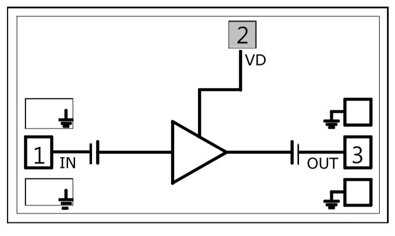
KDA16262
2–18 GHz · GaAs pHEMT MMIC bare die
Functional diagram reference.
View KDA16262 specifications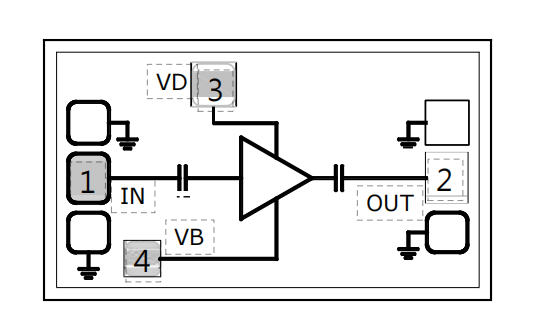
KDA1714
12–28 GHz · GaAs pHEMT MMIC bare die
Functional diagram reference.
View KDA1714 specifications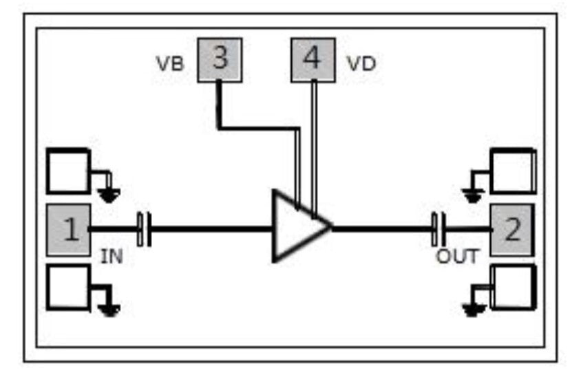
KDA18052
18–40 GHz · GaAs pHEMT MMIC bare die
Functional diagram reference.
View KDA18052 specificationsSelection & Supply
Define the die and evaluation requirements for your project.
Include the RF performance, die requirements and order details needed to assess the model and supplied configuration.
Band, gain and noise
State the working frequencies, required gain, noise-figure target and output P1dB. Include the reference mode and measurement conditions used for your acceptance criteria.
Dimensions and documentation
Specify MMIC bare-die procurement, available mechanical space and DC requirements. Request the current die outline, model specification and any evaluation information required by your engineering team.
Evaluation quantity and delivery
Include the selected KDA model, evaluation or order quantity, destination and required date. Confirm the supplied revision, handling and packaging requirements, sample availability and lead time with the quotation.
Selection FAQ
Questions before specifying low-noise amplifier die.
What delivery form do these nine models use?
These models are GaAs pHEMT MMIC low-noise amplifiers in bare-die form. Specify the exact model and die requirements in your inquiry. For connectorized hardware, review the separate RF low-noise amplifier module range.
How should I compare the typical specifications?
Compare values using the reference mode shown in each row. The table uses a +5 V supply reference and a 50 Ω electrical test system. Typical figures are indicative; request frequency-dependent performance and the applicable specification for the conditions used in your project.
How do I choose between models with overlapping bands?
Start with the actual frequencies your hardware must cover, then compare typical gain, noise figure, output P1dB, DC requirements and die dimensions. Include your performance targets and acceptance conditions when requesting a model recommendation or quotation.
What should I include in an OEM die inquiry?
Include the KDA model or required frequency band, RF performance targets, reference operating mode, DC and dimensional constraints, evaluation or order quantity, destination and timeline. State the model documentation and delivery packaging information your team needs.
OEM Die Procurement
Request low-noise amplifier die specifications or a quotation.
On Contact, select OEM Modules & Boards. Include the KDA model or required frequency band, your RF and die requirements, quantity, destination and timeline so we can review the appropriate model and supplied configuration.